


Request Quote
(Ships tomorrow)
LHL08TB223JS Equivalent & Substitute Parts
Part Overview
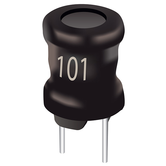
The LHL08TB223JS is a 22 mH fixed unshielded inductor manufactured by Taiyo Yuden, designed for through-hole mounting applications. This component features a radial, vertical cylinder package with a maximum DC resistance of 82 Ohm and a current rating of 44 mA. The part is classified as obsolete, necessitating identification of equivalent substitute components for ongoing design requirements and procurement needs.
Substiute Parts
Key Parameters
| Parameter | Value |
|---|---|
| Inductance | 22 mH |
| Current Rating | 44 mA |
| DC Resistance (DCR) | 82 Ohm Max |
| Shielding | Unshielded |
| Mounting Type | Through Hole |
| Package / Case | Radial, Vertical Cylinder |
| Operating Temperature Range | -25°C ~ 105°C |
| Material - Core | Ferrite |
| Tolerance | ±5% |
| RoHS Status | ROHS3 Compliant |
Substitute Part Grouping Explanation
Substitute components for the LHL08TB223JS are identified based on the following critical parameters that determine functional equivalence:
Primary Matching Criteria:
- Inductance value: 22 mH (exact match required)
- Mounting type: Through hole (mechanical compatibility)
- Package configuration: Radial, vertical cylinder (form factor compatibility)
- Core material: Ferrite (electrical performance characteristics)
- Shielding: Unshielded (electromagnetic environment compatibility)
Secondary Compatibility Parameters:
- Current rating: Substitute must equal or exceed the 44 mA requirement
- DC resistance: Substitute DCR must be compatible with circuit design specifications
- Operating temperature range: Substitute must support the required thermal environment
- RoHS compliance: Substitute must maintain regulatory compliance status
The RLB0913-223K from Bourns Inc. qualifies as a substitute based on matching inductance, mounting type, package configuration, core material, and shielding characteristics. Differences in current rating, DC resistance, and tolerance are within acceptable engineering parameters for component substitution.
Parameter Comparison
| Parameter | LHL08TB223JS (Taiyo Yuden) | RLB0913-223K (Bourns Inc.) |
|---|---|---|
| Inductance | 22 mH | 22 mH |
| Tolerance | ±5% | ±10% |
| Current Rating (Amps) | 44 mA | 80 mA |
| DC Resistance (DCR) | 82 Ohm Max | 56 Ohm |
| Shielding | Unshielded | Unshielded |
| Material - Core | Ferrite | Ferrite |
| Operating Temperature Range | -25°C ~ 105°C | -55°C ~ 125°C |
| Mounting Type | Through Hole | Through Hole |
| Package / Case | Radial, Vertical Cylinder | Radial, Vertical Cylinder |
| Size / Dimension | 0.354" Dia (9.00mm) | 0.335" Dia (8.50mm) |
| Height - Seated (Max) | 0.374" (9.50mm) | 0.492" (12.50mm) |
| RoHS Status | ROHS3 Compliant | ROHS3 Compliant |
| Product Status | Obsolete | Active |
Engineering Selection Recommendations
The RLB0913-223K from Bourns Inc. is an active product suitable for substitution of the obsolete LHL08TB223JS. Both components maintain ROHS3 compliance and share identical inductance values, core material, shielding configuration, and mounting methodology.
The RLB0913-223K provides enhanced current handling capability at 80 mA compared to the 44 mA rating of the LHL08TB223JS, with lower DC resistance at 56 Ohm versus 82 Ohm maximum. The substitute component operates across a wider temperature range (-55°C ~ 125°C) compared to the original part (-25°C ~ 105°C).
Physical dimensions differ slightly: the RLB0913-223K has a smaller diameter (0.335" versus 0.354") but greater height (0.492" versus 0.374"). These dimensional variations require verification against printed circuit board layout constraints and available mounting space.
The tolerance specification of the substitute is ±10% compared to ±5% for the original part. Circuit design must accommodate this increased tolerance range.
Frequently Asked Questions (FAQ)
Q: Can the RLB0913-223K directly replace the LHL08TB223JS in existing designs?
A: The RLB0913-223K matches the critical electrical parameters (22 mH inductance, ferrite core, unshielded configuration, through-hole mounting, radial vertical cylinder package). Physical dimensions differ, requiring verification of PCB layout compatibility. The substitute's lower DCR (56 Ohm vs. 82 Ohm) and higher current rating (80 mA vs. 44 mA) are advantageous for most applications.
Q: What are the key differences between these two inductors?
A: Primary differences include: DC resistance (56 Ohm vs. 82 Ohm), current rating (80 mA vs. 44 mA), inductance tolerance (±10% vs. ±5%), operating temperature range (-55°C to 125°C vs. -25°C to 105°C), and physical dimensions (height 0.492" vs. 0.374"). Electrical inductance value and core material are identical.
Q: Does the RLB0913-223K fit the same PCB footprint?
A: The RLB0913-223K has a smaller diameter (0.335" vs. 0.354") but greater height (0.492" vs. 0.374"). PCB layout verification is required to confirm mounting compatibility. The radial, vertical cylinder configuration remains consistent between both components.
Q: Are both components RoHS compliant?
A: Yes, both the LHL08TB223JS and RLB0913-223K are ROHS3 compliant, maintaining regulatory compliance for restricted substance requirements.
Q: What is the significance of the lower DC resistance in the substitute part?
A: The RLB0913-223K exhibits 56 Ohm DC resistance compared to 82 Ohm maximum for the LHL08TB223JS. Lower DCR reduces resistive losses and heat generation in the inductor, improving circuit efficiency. Circuit design must account for this parameter change in impedance calculations.
Q: Why does the substitute have a wider operating temperature range?
A: The RLB0913-223K operates from -55°C to 125°C compared to -25°C to 105°C for the LHL08TB223JS. This extended range provides greater thermal margin for applications requiring operation in extreme temperature environments. Applications limited to the original temperature range remain fully compatible with the substitute.
Q: How does the tolerance difference affect circuit performance?
A: The RLB0913-223K specifies ±10% inductance tolerance compared to ±5% for the LHL08TB223JS. Circuit designs must accommodate the wider tolerance band of the substitute component. Critical applications requiring tighter inductance control may require component selection or tuning procedures.
Alternative Parts

SJ6012L2TP
Littelfuse Inc.
6 Alternative Parts

JMK107BBJ476MA-RE
Taiyo Yuden
10 Alternative Parts

GMK107BBJ475MA-T
Taiyo Yuden
5 Alternative Parts
SJ6020N2ARP
Littelfuse Inc.
3 Alternative Parts
SJ6025R2ATP
Littelfuse Inc.
4 Alternative Parts

2474-05L
API Delevan Inc.
1 Alternative Parts

4590R-684K
API Delevan Inc.
1 Alternative Parts

CM6560R-334
API Delevan Inc.
1 Alternative Parts

CM6460-104
API Delevan Inc.
1 Alternative Parts

5526-12
API Delevan Inc.
1 Alternative Parts