


Request Quote
(Ships tomorrow)
LF411ACN/NOPB Equivalent & Substitute Parts
Part Overview
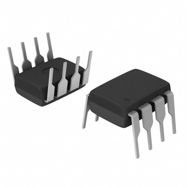
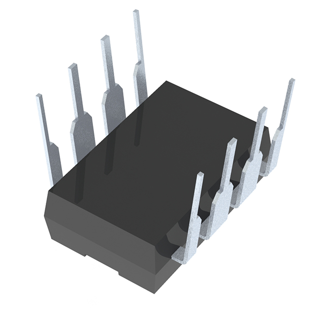
The LF411ACN/NOPB is a J-FET input operational amplifier manufactured by Texas Instruments, housed in an 8-DIP package. This device is classified as obsolete, though 35,768 units remain in stock as new original inventory. The LF411ACN/NOPB belongs to the BI-FET II™ series and is designed for applications requiring low input bias current and high input impedance characteristics typical of J-FET amplifier topologies.
Due to its obsolete product status, identifying equivalent and substitute parts is essential for design continuity, long-term supply chain planning, and new product development. Substitute parts must maintain functional compatibility through matching amplifier type, package configuration, and critical electrical parameters within acceptable operating ranges.
Substiute Parts
Key Parameters
| Parameter | LF411ACN/NOPB Value | Unit | Substitution Relevance |
|---|---|---|---|
| Amplifier Type | J-FET | — | Critical: Determines input stage topology |
| Number of Circuits | 1 | — | Critical: Single amplifier per package |
| Package / Case | 8-DIP (0.300", 7.62mm) | — | Critical: Physical and electrical compatibility |
| Slew Rate | 15 | V/µs | Important: Transient response capability |
| Gain Bandwidth Product | 4 | MHz | Important: Frequency response characteristic |
| Current - Input Bias | 50 | pA | Important: Input stage leakage current |
| Voltage - Input Offset | 300 | µV | Important: DC accuracy specification |
| Current - Supply | 1.8 | mA | Important: Power consumption |
| Voltage - Supply Span (Min) | 10 | V | Critical: Minimum operating voltage |
| Voltage - Supply Span (Max) | 44 | V | Critical: Maximum operating voltage |
| Operating Temperature | 0 to 70 | °C | Important: Thermal operating range |
| Mounting Type | Through Hole | — | Critical: PCB assembly compatibility |
| RoHS Status | ROHS3 Compliant | — | Important: Environmental compliance |
Substitute Part Grouping Explanation
Substitution logic for the LF411ACN/NOPB is based on strict parameter matching across the following criteria:
Primary Compatibility Requirements:
- Amplifier Type: J-FET (maintains input stage characteristics)
- Package / Case: 8-DIP (0.300", 7.62mm) (ensures physical and pin compatibility)
- Mounting Type: Through Hole (PCB assembly compatibility)
- Operating Temperature: 0°C to 70°C (standard commercial range)
Secondary Compatibility Parameters:
- Voltage - Supply Span (Min): ≥ 10 V (minimum supply requirement)
- Voltage - Supply Span (Max): ≥ 44 V (maximum supply capability)
- Current - Input Bias: ≤ 50 pA (low input leakage)
- Voltage - Input Offset: ≤ 300 µV (DC accuracy)
- Slew Rate: ≥ 12 V/µs (transient response)
- Gain Bandwidth Product: ≥ 3 MHz (frequency response)
Compliance Requirements:
- RoHS3 Compliant
- REACH Unaffected
- Active or Obsolete product status (both acceptable for substitution)
Substitute parts are grouped into two categories: Direct J-FET Substitutes (matching amplifier type) and Alternative Topology (general-purpose amplifiers with compatible electrical performance).
Parameter Comparison
| Part Number | Manufacturer | Amplifier Type | Slew Rate (V/µs) | GBW (MHz) | Input Bias (pA) | Input Offset (µV) | Supply Current (mA) | Supply Min (V) | Supply Max (V) | Product Status |
|---|---|---|---|---|---|---|---|---|---|---|
| LF411ACN/NOPB | Texas Instruments | J-FET | 15 | 4 | 50 | 300 | 1.8 | 10 | 44 | Obsolete |
| LF411CP | Texas Instruments | J-FET | 13 | 3 | 50 | 800 | 2 | 7 | 36 | Active |
| AD711JNZ | Analog Devices Inc. | J-FET | 20 | 4 | 15 | 300 | 2.5 | 9 | 36 | Active |
| AD711KNZ | Analog Devices Inc. | J-FET | 20 | 4 | 15 | 200 | 2.5 | 9 | 36 | Active |
| LT1055CN8#PBF | Analog Devices Inc. | J-FET | 12 | 4.5 | 30 | 120 | 2.8 | 10 | 36 | Active |
| LT1056CN8#PBF | Analog Devices Inc. | J-FET | 14 | 5.5 | 30 | 140 | 5 | 10 | 36 | Active |
| LT1792ACN8#PBF | Analog Devices Inc. | J-FET | 3.4 | 5.6 | 300 | 200 | 4.2 | 9 | 40 | Active |
| LT1792CN8#PBF | Analog Devices Inc. | J-FET | 3.4 | 5.6 | 300 | 200 | 4.2 | 9 | 40 | Active |
| LT1792IN8#PBF | Analog Devices Inc. | J-FET | 3.4 | 5.6 | 300 | 200 | 4.2 | 9 | 40 | Active |
| LT1793ACN8#PBF | Analog Devices Inc. | J-FET | 3.4 | 4.2 | 3 | 250 | 4.2 | 9 | 40 | Active |
| AD548KNZ | Analog Devices Inc. | General Purpose | 1.8 | 1 | 30 | 300 | 0.17 | 9 | 36 | Active |
Engineering Selection Recommendations
Tier 1: Direct Substitutes (Preferred)
The following parts maintain J-FET amplifier topology, 8-DIP package configuration, and supply voltage compatibility with the LF411ACN/NOPB:
-
AD711JNZ and AD711KNZ: Active product status from Analog Devices Inc. Both devices exceed the original slew rate specification (20 V/µs vs. 15 V/µs) and maintain 4 MHz gain bandwidth product. AD711KNZ offers superior input offset voltage (200 µV vs. 300 µV). Supply voltage range (9–36 V) is compatible with the original 10–44 V specification for applications operating within 10–36 V.
-
LT1055CN8#PBF: Active product with J-FET topology. Provides 4.5 MHz gain bandwidth product and superior input offset voltage (120 µV). Supply range 10–36 V aligns with the original minimum requirement. Slew rate of 12 V/µs is within acceptable range.
-
LT1056CN8#PBF: Active product with enhanced 5.5 MHz gain bandwidth product. Supply range 10–36 V meets minimum requirements. Higher supply current (5 mA vs. 1.8 mA) must be evaluated for power budget applications.
Tier 2: Alternative Consideration
- LF411CP: Same manufacturer (Texas Instruments) and base product family. Active product status. However, reduced gain bandwidth product (3 MHz vs. 4 MHz) and increased input offset voltage (800 µV vs. 300 µV) represent performance degradation. Supply voltage maximum reduced to 36 V. Suitable only where performance reduction is acceptable.
Tier 3: Limited Compatibility
-
LT1792 Series (LT1792ACN8#PBF, LT1792CN8#PBF, LT1792IN8#PBF): J-FET topology with active status. However, significantly reduced slew rate (3.4 V/µs vs. 15 V/µs) and higher input bias current (300 pA vs. 50 pA) limit applicability to low-frequency, low-impedance circuits only.
-
LT1793ACN8#PBF: Exceptional input bias current (3 pA) but reduced slew rate (3.4 V/µs) and lower gain bandwidth product (4.2 MHz). Suitable for ultra-low-bias-current applications only.
Not Recommended
- AD548KNZ: General-purpose amplifier topology (not J-FET). Significantly reduced slew rate (1.8 V/µs), gain bandwidth product (1 MHz), and supply current (170 µA). Fundamentally different performance characteristics make this unsuitable for direct substitution.
All recommended substitutes maintain RoHS3 compliance and REACH unaffected status, ensuring regulatory compatibility.
Frequently Asked Questions (FAQ)
Q1: Can I directly replace LF411ACN/NOPB with LF411CP?
Both parts share the same base product number and J-FET topology in 8-DIP packaging. However, LF411CP exhibits reduced gain bandwidth product (3 MHz vs. 4 MHz) and significantly higher input offset voltage (800 µV vs. 300 µV). Substitution is possible only if your circuit tolerates these performance reductions. The reduced maximum supply voltage (36 V vs. 44 V) may also be limiting.
Q2: What is the primary difference between AD711JNZ and AD711KNZ?
Both are Analog Devices J-FET operational amplifiers in 8-DIP packages with identical slew rate (20 V/µs) and gain bandwidth product (4 MHz). The key difference is input offset voltage: AD711KNZ specifies 200 µV versus AD711JNZ at 300 µV. Select AD711KNZ for applications requiring tighter DC accuracy.
Q3: Why is AD548KNZ listed as a substitute if it is a general-purpose amplifier?
AD548KNZ was included in the original LF411ACN/NOPB substitute list provided in the input data. However, its general-purpose topology, significantly lower slew rate (1.8 V/µs), and reduced gain bandwidth product (1 MHz) make it unsuitable for direct substitution in most applications. Use only if your circuit operates at very low frequencies and can tolerate reduced performance.
Q4: Are the LT1792 series parts suitable replacements?
LT1792 devices (ACN8, CN8, IN8 variants) maintain J-FET topology and 8-DIP packaging. However, their slew rate of 3.4 V/µs is substantially lower than the original 15 V/µs specification. These parts are suitable only for low-frequency, precision DC applications where slew rate is not critical. The higher input bias current (300 pA vs. 50 pA) may also be problematic for high-impedance circuits.
Q5: What is the difference between LT1792ACN8#PBF, LT1792CN8#PBF, and LT1792IN8#PBF?
All three variants share identical electrical specifications (slew rate, gain bandwidth product, input bias current, input offset voltage, supply current, and supply voltage range). The difference is operating temperature range: LT1792ACN8#PBF and LT1792CN8#PBF operate 0°C to 70°C (commercial), while LT1792IN8#PBF operates −40°C to 85°C (industrial). Select based on your thermal environment requirements.
Q6: Can I use LT1055CN8#PBF or LT1056CN8#PBF in a 44 V supply application?
No. Both LT1055CN8#PBF and LT1056CN8#PBF specify a maximum supply voltage of 36 V, while the original LF411ACN/NOPB supports 44 V. If your application requires operation above 36 V, these substitutes are not suitable. Verify your actual supply voltage requirement before selection.
Q7: Which substitute offers the best overall performance match to LF411ACN/NOPB?
AD711JNZ and AD711KNZ provide the closest performance match: identical 4 MHz gain bandwidth product, superior slew rate (20 V/µs vs. 15 V/µs), lower input bias current (15 pA vs. 50 pA), and active product status. AD711KNZ is preferred if input offset voltage accuracy is critical (200 µV vs. 300 µV). Both operate within compatible supply voltage ranges for most applications (9–36 V vs. original 10–44 V).
Q8: Are all substitute parts RoHS3 compliant?
Yes. All substitute parts listed in this document are RoHS3 compliant and REACH unaffected, ensuring regulatory compatibility with modern manufacturing and environmental standards.
Q9: What is the significance of "Active" versus "Obsolete" product status?
Active products are currently manufactured and supported by the supplier, ensuring long-term availability and technical support. Obsolete products are no longer manufactured but may remain available from inventory. The LF411ACN/NOPB is obsolete; substitutes with Active status (AD711 series, LT1055, LT1056, LT1792 series, LT1793) provide better long-term supply chain security.
Q10: Can I use these substitutes in new product designs?
Yes. All substitute parts with Active product status are suitable for new designs. However, conduct thorough circuit simulation and prototype testing to verify performance compatibility, particularly for applications sensitive to slew rate, input bias current, or supply voltage range. The LF411CP, despite Active status, shows performance degradation and should be evaluated carefully.
Alternative Parts

SJ6012L2TP
Littelfuse Inc.
6 Alternative Parts

JMK107BBJ476MA-RE
Taiyo Yuden
10 Alternative Parts

GMK107BBJ475MA-T
Taiyo Yuden
5 Alternative Parts
SJ6020N2ARP
Littelfuse Inc.
3 Alternative Parts
SJ6025R2ATP
Littelfuse Inc.
4 Alternative Parts

2474-05L
API Delevan Inc.
1 Alternative Parts

4590R-684K
API Delevan Inc.
1 Alternative Parts

CM6560R-334
API Delevan Inc.
1 Alternative Parts

CM6460-104
API Delevan Inc.
1 Alternative Parts

5526-12
API Delevan Inc.
1 Alternative Parts