


Request Quote
(Ships tomorrow)
KSP10BU Equivalent & Substitute Parts
Part Overview
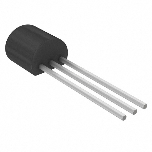
The KSP10BU is an RF transistor manufactured by onsemi, classified as a Bipolar Junction Transistor (BJT) with NPN polarity. This component operates at a maximum collector-emitter breakdown voltage of 25V and supports RF applications up to 650MHz with a maximum power dissipation of 350mW. The device is packaged in a through-hole TO-92-3 configuration and maintains Active product status with full RoHS3 compliance.
Substitute parts are identified when equivalent electrical performance can be achieved within the constraints of specific application requirements, accounting for differences in mounting technology, frequency capability, voltage ratings, and power handling characteristics.
Substiute Parts
Key Parameters
| Parameter | KSP10BU |
|---|---|
| Manufacturer | onsemi |
| Transistor Type | NPN |
| Voltage - Collector Emitter Breakdown (Max) | 25V |
| Frequency - Transition | 650MHz |
| Power - Max | 350mW |
| DC Current Gain (hFE) (Min) @ Ic, Vce | 60 @ 4mA, 10V |
| Operating Temperature (TJ) | 150°C |
| Mounting Type | Through Hole |
| Package / Case | TO-92-3 |
| Product Status | Active |
| RoHS Status | ROHS3 Compliant |
Substitute Part Grouping Explanation
Substitution eligibility for the KSP10BU is determined by the following critical parameters:
Transistor Type: All substitutes must be NPN polarity bipolar junction transistors to maintain circuit functionality and biasing compatibility.
Voltage Rating: The collector-emitter breakdown voltage of substitute parts must equal or exceed the 25V maximum rating of the KSP10BU to ensure safe operation within the same voltage domain.
Frequency Capability: Substitute parts must support RF operation at or above 650MHz transition frequency to maintain performance in the intended application bandwidth.
Power Dissipation: Maximum power rating must be sufficient for the thermal requirements of the application, with the KSP10BU baseline at 350mW.
Operating Temperature: All substitutes must support the 150°C maximum junction temperature to ensure reliability across the full operating range.
Product Status and Compliance: Substitute parts must maintain Active product status and comply with RoHS3 and REACH regulations to meet current procurement and environmental standards.
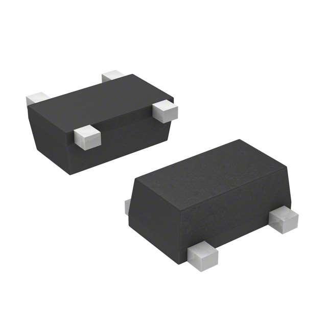
The three identified substitute parts (2SC5087R, BFP196E6327HTSA1, and BFP540FESDH6327XTSA1) represent different trade-offs in these parameters, with variations in mounting technology (surface mount versus through-hole), frequency capability (8GHz, 7.5GHz, and 30GHz respectively), and voltage ratings (12V and 5V).
Parameter Comparison
| Parameter | KSP10BU | 2SC5087R(TE85L,F) | BFP196E6327HTSA1 | BFP540FESDH6327XTSA1 |
|---|---|---|---|---|
| Manufacturer | onsemi | Toshiba Semiconductor and Storage | Infineon Technologies | Infineon Technologies |
| Transistor Type | NPN | NPN | NPN | NPN |
| Voltage - Collector Emitter Breakdown (Max) | 25V | 12V | 12V | 5V |
| Frequency - Transition | 650MHz | 8GHz | 7.5GHz | 30GHz |
| Power - Max | 350mW | 150mW | 700mW | 250mW |
| DC Current Gain (hFE) (Min) @ Ic, Vce | 60 @ 4mA, 10V | 120 @ 20mA, 10V | 70 @ 50mA, 8V | 50 @ 20mA, 3.5V |
| Current - Collector (Ic) (Max) | Not specified | 80mA | 150mA | 80mA |
| Operating Temperature (TJ) | 150°C | 125°C | 150°C | 150°C |
| Mounting Type | Through Hole | Surface Mount | Surface Mount | Surface Mount |
| Package / Case | TO-92-3 | SMQ | PG-SOT-143-3D | 4-TSFP |
| Product Status | Active | Active | Active | Active |
| RoHS Status | ROHS3 Compliant | RoHS Compliant | ROHS3 Compliant | ROHS3 Compliant |
Engineering Selection Recommendations
KSP10BU Primary Application: The KSP10BU is suitable for RF applications requiring through-hole mounting, 25V voltage headroom, and moderate frequency operation up to 650MHz. This part maintains Active status with full RoHS3 and REACH compliance, making it appropriate for current production designs.
2SC5087R(TE85L,F) Consideration: This Toshiba substitute provides higher frequency capability (8GHz) and higher DC current gain (120 @ 20mA, 10V) but operates at reduced voltage (12V maximum) and lower power dissipation (150mW). The surface-mount SMQ package requires PCB redesign from the through-hole TO-92-3 configuration. Operating temperature is limited to 125°C, which is 25°C below the KSP10BU maximum. RoHS compliance is confirmed, though not specifically ROHS3 certified.
BFP196E6327HTSA1 Consideration: This Infineon substitute supports 7.5GHz frequency operation with higher power dissipation (700mW) and higher maximum collector current (150mA). Voltage rating is reduced to 12V maximum. The surface-mount PG-SOT-143-3D package requires PCB redesign. Operating temperature matches the KSP10BU at 150°C. Full ROHS3 compliance and REACH unaffected status are confirmed.
BFP540FESDH6327XTSA1 Consideration: This Infineon substitute provides the highest frequency capability (30GHz) with 20dB gain specification and lowest noise figure (0.9dB ~ 1.4dB @ 1.8GHz). However, voltage rating is severely reduced to 5V maximum, and power dissipation is limited to 250mW. The surface-mount 4-TSFP package requires significant PCB redesign. Operating temperature matches the KSP10BU at 150°C. Full ROHS3 compliance and REACH unaffected status are confirmed.
All substitute parts maintain Active product status and meet current regulatory requirements. Selection depends on specific application voltage requirements, frequency bandwidth, power budget, and PCB assembly capabilities.
Frequently Asked Questions (FAQ)
Q: Can the 2SC5087R(TE85L,F) directly replace the KSP10BU in a 25V circuit?
A: No. The 2SC5087R has a maximum collector-emitter breakdown voltage of 12V, which is insufficient for circuits designed for 25V operation. Using this substitute in a 25V circuit will result in device failure.
Q: What is the primary difference between the KSP10BU and the BFP196E6327HTSA1?
A: The KSP10BU is a through-hole TO-92-3 package rated for 25V and 650MHz, while the BFP196E6327HTSA1 is a surface-mount PG-SOT-143-3D package rated for 12V and 7.5GHz. The BFP196 offers higher frequency capability and power dissipation (700mW versus 350mW) but reduced voltage rating and requires PCB redesign.
Q: Is the BFP540FESDH6327XTSA1 suitable for 25V applications?
A: No. The BFP540 is rated for a maximum of 5V collector-emitter breakdown voltage. It is designed for low-voltage, high-frequency RF applications and cannot be used in circuits requiring 25V operation.
Q: Why do all substitute parts use surface-mount packaging while the KSP10BU is through-hole?
A: The substitute parts represent modern RF transistor designs optimized for surface-mount assembly and higher frequency operation. Through-hole RF transistors like the KSP10BU are less common in current production. Substitution requires PCB redesign and assembly process changes.
Q: Are all substitute parts RoHS3 compliant?
A: The BFP196E6327HTSA1 and BFP540FESDH6327XTSA1 are explicitly ROHS3 compliant. The 2SC5087R is RoHS compliant but not specifically certified as ROHS3. For applications requiring ROHS3 certification, the Infineon parts are preferred.
Q: What is the operating temperature limitation of the 2SC5087R?
A: The 2SC5087R has a maximum junction temperature of 125°C, which is 25°C lower than the KSP10BU (150°C). This may limit thermal margin in applications operating near the upper temperature range.
Q: Can the KSP10BU be replaced with the BFP540FESDH6327XTSA1 in a 650MHz application?
A: The BFP540 supports 30GHz operation, which exceeds the 650MHz requirement. However, the 5V voltage rating is incompatible with 25V circuits. Substitution is only possible if the circuit voltage is redesigned to 5V or lower.
Q: What mounting considerations apply when substituting the KSP10BU?
A: The KSP10BU uses through-hole TO-92-3 mounting for manual or wave soldering. All substitute parts use surface-mount technology (SMQ, PG-SOT-143-3D, or 4-TSFP packages), requiring reflow soldering equipment and PCB layout redesign with appropriate pad patterns and trace routing for RF performance.
Alternative Parts

SJ6012L2TP
Littelfuse Inc.
6 Alternative Parts

JMK107BBJ476MA-RE
Taiyo Yuden
10 Alternative Parts

GMK107BBJ475MA-T
Taiyo Yuden
5 Alternative Parts
SJ6020N2ARP
Littelfuse Inc.
3 Alternative Parts
SJ6025R2ATP
Littelfuse Inc.
4 Alternative Parts

2474-05L
API Delevan Inc.
1 Alternative Parts

4590R-684K
API Delevan Inc.
1 Alternative Parts

CM6560R-334
API Delevan Inc.
1 Alternative Parts

CM6460-104
API Delevan Inc.
1 Alternative Parts

5526-12
API Delevan Inc.
1 Alternative Parts