


Request Quote
(Ships tomorrow)
IXTY8N65X2 N-Channel 650V 8A MOSFET Equivalent & Substitute Parts
Part Overview
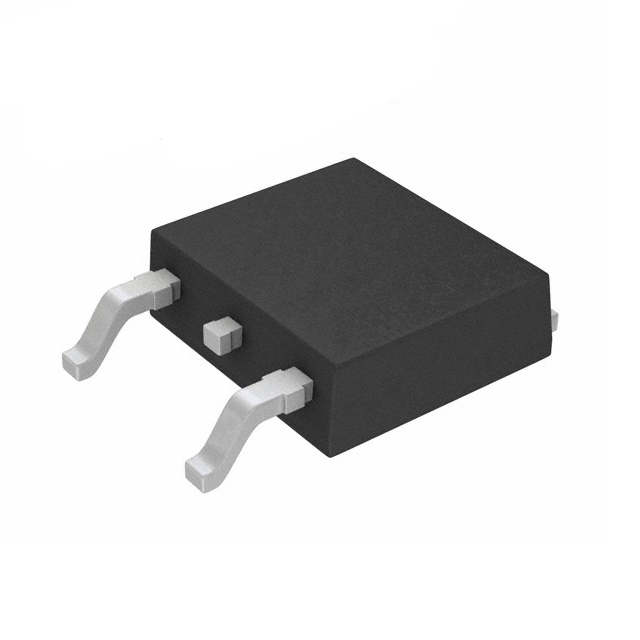
The IXTY8N65X2 is an N-Channel MOSFET manufactured by IXYS in the Ultra X2 series, rated for 650V drain-to-source voltage and 8A continuous drain current at 25°C. This device is housed in a TO-252-3 (DPAK) surface mount package and is designed for high-voltage switching applications requiring 150W power dissipation capability. The part is Active status and RoHS3 compliant with unlimited moisture sensitivity rating (MSL 1).
Equivalent and substitute parts are identified based on matching or closely aligned electrical specifications including drain-to-source voltage rating, continuous drain current, on-resistance characteristics, gate charge, and thermal performance within the same or compatible package types. Substitutes enable design flexibility, supply chain alternatives, and performance optimization across different manufacturer technologies.
Substiute Parts
Key Parameters
| Parameter | IXTY8N65X2 | Unit |
|---|---|---|
| FET Type | N-Channel | — |
| Drain-to-Source Voltage (Vdss) | 650 | V |
| Continuous Drain Current (Id) @ 25°C | 8 | A |
| On-Resistance (Rds On) @ 4A, 10V | 500 | mOhm |
| Gate Threshold Voltage (Vgs(th)) @ 250µA | 5 | V |
| Gate Charge (Qg) @ 10V | 12 | nC |
| Input Capacitance (Ciss) @ 25V | 800 | pF |
| Power Dissipation (Max) | 150 | W |
| Operating Temperature Range | -55 to 150 | °C |
| Package Type | TO-252-3 (DPAK) | — |
| Mounting Type | Surface Mount | — |
| RoHS Status | ROHS3 Compliant | — |
| MSL Rating | 1 (Unlimited) | — |
Substitute Part Grouping Explanation
Substitute parts for the IXTY8N65X2 are classified based on the following substitution criteria:
Primary Substitution Parameters:
- Drain-to-Source Voltage (Vdss): 600V to 650V range
- Continuous Drain Current (Id): 6A to 11A range
- On-Resistance (Rds On): 450mOhm to 600mOhm @ 10V gate drive
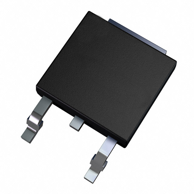
- Package Type: TO-252-3 (DPAK) surface mount
- Technology: N-Channel MOSFET (Metal Oxide)
- Compliance: RoHS3 compliant, EAR99 classification
Substitution Logic:
Parts with 650V Vdss rating and 8A Id rating provide direct electrical equivalence with identical voltage and current handling. Parts with 600V Vdss rating are acceptable substitutes where the application does not require the full 650V margin, offering improved on-resistance and thermal performance. Parts with higher current ratings (9A to 11A) at 600V or 650V provide performance headroom for thermal management and switching reliability. All substitute parts maintain TO-252-3 package compatibility, surface mount configuration, and RoHS3 compliance.
Gate charge, input capacitance, and on-resistance variations across substitutes reflect different semiconductor technology generations (MDmesh, CoolMOS, FDmesh, Ultra X2 series) and affect switching speed, gate drive requirements, and conduction losses.
Parameter Comparison
| Part Number | Manufacturer | Vdss (V) | Id @ 25°C (A) | Rds On @ 10V (mOhm) | Qg @ 10V (nC) | Ciss @ Vds (pF) | Power Diss. (W) | Temp Range (°C) | Package |
|---|---|---|---|---|---|---|---|---|---|
| IXTY8N65X2 | IXYS | 650 | 8 | 500 @ 4A | 12 @ 10V | 800 @ 25V | 150 | -55 to 150 | TO-252-3 |
| STD12N65M2 | STMicroelectronics | 650 | 8 | 500 @ 4A | 16.5 @ 10V | 535 @ 100V | 85 | -55 to 150 | TO-252-3 |
| STD11N65M5 | STMicroelectronics | 650 | 9 | 480 @ 4.5A | 17 @ 10V | 620 @ 100V | 85 | -55 to 150 | TO-252-3 |
| STD11NM65N | STMicroelectronics | 650 | 11 | 455 @ 5.5A | 29 @ 10V | 800 @ 50V | 110 | -55 to 150 | TO-252-3 |
| SPD07N60C3ATMA1 | Infineon Technologies | 600 | 7.3 | 600 @ 4.6A | 27 @ 10V | 790 @ 25V | 83 | -55 to 150 | TO-252-3 |
| STD10N60M2 | STMicroelectronics | 600 | 7.5 | 600 @ 3A | 13.5 @ 10V | 400 @ 100V | 85 | -55 to 150 | TO-252-3 |
| STD10NM60ND | STMicroelectronics | 600 | 8 | 600 @ 4A | 20 @ 10V | 577 @ 50V | 70 | -55 to 150 | TO-252-3 |
| STD10NM60N | STMicroelectronics | 600 | 10 | 550 @ 4A | 19 @ 10V | 540 @ 50V | 70 | -55 to 150 | TO-252-3 |
| STD11NM60ND | STMicroelectronics | 600 | 10 | 450 @ 5A | 30 @ 10V | 850 @ 50V | 90 | -55 to 150 | TO-252-3 |
| STD12N60M2 | STMicroelectronics | 600 | 9 | 450 @ 4.5A | 16 @ 10V | 538 @ 100V | 85 | -55 to 150 | TO-252-3 |
| IPD60R600P7SAUMA1 | Infineon Technologies | 600 | 6 | 600 @ 1.7A | 9 @ 10V | 363 @ 400V | 30 | -40 to 150 | TO-252-3 |
Engineering Selection Recommendations
Direct Equivalents (650V, 8A Rating):
STD12N65M2 and STD11N65M5 provide electrical equivalence to the IXTY8N65X2 with identical or superior voltage and current ratings. Both parts are RoHS3 compliant, MSL 1 rated, and support the full -55°C to 150°C operating temperature range. STD12N65M2 matches the exact 650V/8A specification with 500mOhm on-resistance, while STD11N65M5 offers 9A capability with improved 480mOhm on-resistance. STD11NM65N extends current handling to 11A at 650V with 455mOhm on-resistance, suitable for applications requiring thermal margin.
600V Substitutes (Reduced Voltage Rating):
Parts rated for 600V Vdss (STD10N60M2, STD10NM60ND, STD10NM60N, STD11NM60ND, STD12N60M2, SPD07N60C3ATMA1) are acceptable where application voltage stress does not exceed 600V. These parts generally exhibit lower on-resistance and improved thermal performance compared to 650V-rated devices. STD10NM60N and STD11NM60ND support 10A continuous current with on-resistance of 550mOhm and 450mOhm respectively, providing performance headroom. All 600V substitutes maintain RoHS3 compliance and -55°C to 150°C temperature range except IPD60R600P7SAUMA1, which operates from -40°C.
Compliance and Certification:
All substitute parts carry RoHS3 compliance, EAR99 export classification, and REACH unaffected status, matching the IXTY8N65X2 regulatory profile. MSL ratings are uniformly 1 (Unlimited) across STMicroelectronics and IXYS parts, with Infineon IPD60R600P7SAUMA1 rated MSL 3 (168 hours). Package compatibility is maintained across all substitutes in TO-252-3 (DPAK) configuration.
Frequently Asked Questions (FAQ)
Q: Can STD12N65M2 directly replace IXTY8N65X2 in existing designs?
A: Yes. STD12N65M2 matches the IXTY8N65X2 specification of 650V Vdss, 8A continuous drain current, and 500mOhm on-resistance at 10V gate drive. Both parts use TO-252-3 package, support -55°C to 150°C operation, and are RoHS3 compliant with MSL 1 rating. Gate charge differs (16.5nC vs. 12nC), requiring verification of gate driver capability for switching frequency and rise/fall time performance.
Q: What is the difference between 600V and 650V rated substitutes?
A: 650V-rated parts (STD12N65M2, STD11N65M5, STD11NM65N) provide full voltage margin for the IXTY8N65X2 application. 600V-rated substitutes (STD10N60M2, STD10NM60ND, STD12N60M2, SPD07N60C3ATMA1) are suitable only where peak drain-to-source voltage remains below 600V. 600V parts typically exhibit lower on-resistance and improved thermal performance due to different semiconductor technology. Selection depends on application voltage stress and thermal requirements.
Q: Are there current rating differences between substitutes?
A: Yes. The IXTY8N65X2 is rated 8A continuous at 25°C. Substitutes range from 6A (IPD60R600P7SAUMA1) to 11A (STD11NM65N). Higher-rated parts (9A to 11A) provide thermal margin and improved reliability in high-current applications. Lower-rated parts (6A to 7.5A) are acceptable only where application current does not exceed their continuous rating.
Q: How do gate charge differences affect circuit design?
A: Gate charge (Qg) varies from 9nC (IPD60R600P7SAUMA1) to 30nC (STD11NM60ND). Higher gate charge requires greater gate driver current or longer switching times. The IXTY8N65X2 specifies 12nC. Substitutes with significantly higher gate charge (27nC to 30nC) may require gate driver re-evaluation for switching frequency and efficiency. Lower gate charge substitutes improve switching speed and reduce gate drive losses.
Q: Is package compatibility guaranteed across all substitutes?
A: All listed substitutes use TO-252-3 (DPAK) surface mount package with identical pin configuration (2 leads + tab). Physical footprint and PCB layout compatibility are maintained. Thermal performance varies due to different die sizes and internal construction; thermal interface material and heatsinking requirements should be verified against individual datasheets.
Q: What is the impact of on-resistance variation on circuit performance?
A: On-resistance (Rds On) ranges from 450mOhm to 600mOhm across substitutes. Lower on-resistance reduces conduction losses and heat generation. The IXTY8N65X2 specifies 500mOhm at 4A, 10V. Substitutes with 450mOhm to 480mOhm (STD11NM60ND, STD11N65M5) reduce power dissipation; those with 600mOhm (SPD07N60C3ATMA1, IPD60R600P7SAUMA1, STD10N60M2) increase conduction losses. Selection depends on thermal budget and efficiency requirements.
Q: Are all substitutes suitable for high-frequency switching applications?
A: Gate charge and input capacitance determine switching speed capability. Lower gate charge (9nC to 16.5nC) enables faster switching with reduced gate driver stress. Higher gate charge (27nC to 30nC) increases switching transition time and gate drive power. Input capacitance ranges from 363pF to 850pF, affecting gate driver impedance matching. Verification against specific switching frequency and gate driver specifications is required.
Q: What is the significance of MSL rating differences?
A: The IXTY8N65X2 carries MSL 1 (Unlimited), indicating no moisture sensitivity restrictions. Most substitutes (STMicroelectronics, IXYS) are also MSL 1. IPD60R600P7SAUMA1 is MSL 3 (168 hours), requiring controlled moisture exposure during storage and assembly. MSL 3 parts must be baked before reflow soldering if storage exceeds 168 hours at specified humidity levels.
Q: Can 600V-rated parts be used in 650V applications?
A: No. 600V-rated parts are not suitable for applications where peak drain-to-source voltage exceeds 600V. Using 600V parts in 650V applications risks device breakdown and failure. Only 650V-rated substitutes (STD12N65M2, STD11N65M5, STD11NM65N) are acceptable for full 650V voltage stress.
Alternative Parts

SJ6012L2TP
Littelfuse Inc.
6 Alternative Parts

JMK107BBJ476MA-RE
Taiyo Yuden
10 Alternative Parts

GMK107BBJ475MA-T
Taiyo Yuden
5 Alternative Parts
SJ6020N2ARP
Littelfuse Inc.
3 Alternative Parts
SJ6025R2ATP
Littelfuse Inc.
4 Alternative Parts

2474-05L
API Delevan Inc.
1 Alternative Parts

4590R-684K
API Delevan Inc.
1 Alternative Parts

CM6560R-334
API Delevan Inc.
1 Alternative Parts

CM6460-104
API Delevan Inc.
1 Alternative Parts

5526-12
API Delevan Inc.
1 Alternative Parts