


Request Quote
(Ships tomorrow)
IXTY44N10T Equivalent & Substitute Parts
Part Overview
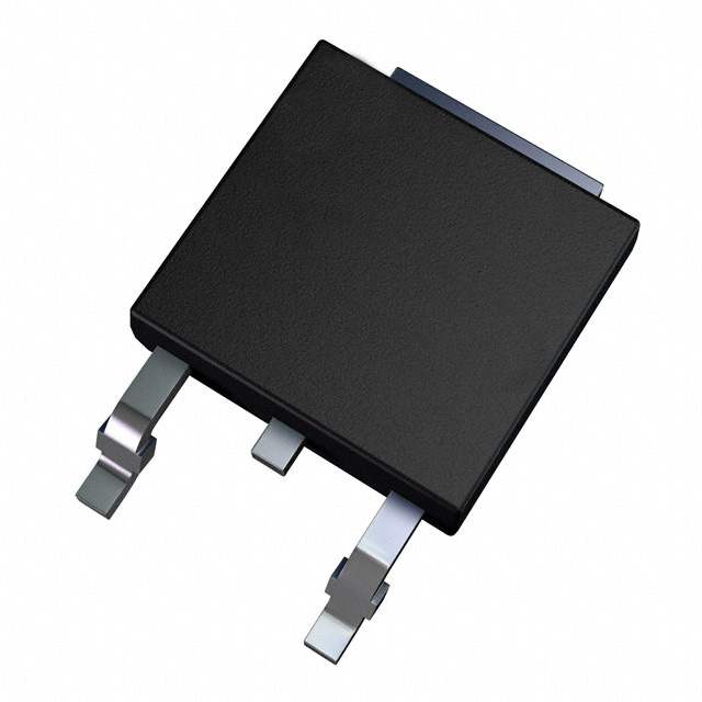
The IXTY44N10T is an N-Channel MOSFET manufactured by IXYS, rated for 100V drain-to-source voltage with 44A continuous drain current at 25°C. This device is housed in a TO-252AA (DPAK) surface mount package and is designed for applications requiring high current switching capability with moderate power dissipation up to 130W. The part is Active status and RoHS3 compliant, with unlimited moisture sensitivity level (MSL 1).
Equivalent and substitute parts are identified based on matching or exceeding critical electrical parameters including drain-to-source voltage rating, continuous drain current capability, on-resistance characteristics, gate charge, and compatible surface mount packaging. Substitutes must maintain functional compatibility within the specified operating temperature range of -55°C to 175°C.
Substiute Parts
Key Parameters
| Parameter | Value | Unit |
|---|---|---|
| Drain to Source Voltage (Vdss) | 100 | V |
| Continuous Drain Current (Id) @ 25°C | 44 | A |
| On-Resistance (Rds On Max) @ 22A, 10V | 30 | mOhm |
| Gate Threshold Voltage (Vgs(th)) @ 25µA | 4.5 | V |
| Gate Charge (Qg) @ 10V | 33 | nC |
| Power Dissipation (Max) | 130 | W |
| Operating Temperature Range | -55 to 175 | °C |
| Package Type | TO-252-3 (DPAK) | — |
Substitute Part Grouping Explanation
Substitution eligibility for the IXTY44N10T is determined by the following criteria:
Voltage Rating Compatibility: All substitute parts must maintain a Vdss rating of 100V or greater to ensure safe operation within the original design envelope.
Current Capability: Substitute parts must provide continuous drain current (Id) at 25°C equal to or exceeding 44A to support the same load requirements without thermal derating.
On-Resistance Performance: Rds On values must be comparable to the original specification (30 mOhm @ 22A, 10V) to maintain similar power dissipation and thermal characteristics.
Gate Charge and Switching Characteristics: Gate charge (Qg) and threshold voltage (Vgs(th)) must be within acceptable ranges to ensure compatible gate drive requirements and switching performance.
Package Compatibility: All substitutes must use the TO-252-3 (DPAK) surface mount package to maintain mechanical and thermal interface compatibility.
Compliance and Status: All substitute parts must be Active status with RoHS3 compliance and MSL 1 rating to meet regulatory and manufacturing requirements.
Parameter Comparison
| Parameter | IXTY44N10T | AUIRFR540ZTRL | DMNH10H028SK3-13 | DMNH10H028SK3Q-13 | IRFR540ZTRPBF | IRLR2908TRPBF |
|---|---|---|---|---|---|---|
| Manufacturer | IXYS | Infineon Technologies | Diodes Incorporated | Diodes Incorporated | Infineon Technologies | Infineon Technologies |
| Vdss (V) | 100 | 100 | 100 | 100 | 100 | 80 |
| Id @ 25°C (A) | 44 | 35 | 55 | 55 | 35 | 30 |
| Rds On Max @ 10V (mOhm) | 30 @ 22A | 28.5 @ 21A | 28 @ 20A | 28 @ 20A | 28.5 @ 21A | 28 @ 23A |
| Vgs(th) Max (V) | 4.5 @ 25µA | 4 @ 50µA | 3.3 @ 250µA | 4 @ 250µA | 4 @ 50µA | 2.5 @ 250µA |
| Qg @ 10V (nC) | 33 | 59 | 36 | 36 | 59 | 33 @ 4.5V |
| Power Dissipation Max (W) | 130 (Tc) | 91 (Tc) | 2 (Ta) | 2 (Ta) | 91 (Tc) | 120 (Tc) |
| Operating Temperature (°C) | -55 to 175 | -55 to 175 | -55 to 175 | -55 to 175 | -55 to 175 | -55 to 175 |
| Package | TO-252-3 (DPAK) | DPAK | TO-252-3 | TO-252-3 | TO-252AA (DPAK) | TO-252AA (DPAK) |
| RoHS Status | ROHS3 Compliant | ROHS3 Compliant | ROHS3 Compliant | ROHS3 Compliant | ROHS3 Compliant | ROHS3 Compliant |
| MSL Rating | 1 (Unlimited) | 1 (Unlimited) | 1 (Unlimited) | 1 (Unlimited) | 1 (Unlimited) | 1 (Unlimited) |
Engineering Selection Recommendations
AUIRFR540ZTRL and IRFR540ZTRPBF (Infineon Technologies): These parts share identical electrical specifications and are functionally equivalent alternatives. Both are rated for 100V Vdss with 35A continuous drain current. The on-resistance of 28.5 mOhm is comparable to the original specification. Gate charge is higher at 59 nC, which may require adjusted gate drive timing. Power dissipation is rated at 91W, which is lower than the original 130W. These parts are suitable for applications where the 35A current rating is sufficient and thermal management can accommodate the lower power dissipation rating. Both are Active status with full RoHS3 compliance and MSL 1 rating.
DMNH10H028SK3-13 and DMNH10H028SK3Q-13 (Diodes Incorporated): These parts provide higher continuous drain current at 55A, exceeding the original 44A specification. Both are rated for 100V Vdss with on-resistance of 28 mOhm at 20A, 10V. Gate charge is 36 nC, closely matching the original 33 nC specification. The power dissipation rating of 2W (Ta) differs from the original specification format but indicates thermal performance suitable for the application. These parts are direct mechanical and electrical substitutes with enhanced current capability. Both are Active status with full RoHS3 compliance and MSL 1 rating.
IRLR2908TRPBF (Infineon Technologies): This part is rated for 80V Vdss, which is 20V lower than the original 100V specification. Continuous drain current is 30A, below the original 44A rating. Gate charge of 33 nC matches the original specification exactly. Power dissipation is rated at 120W (Tc), comparable to the original 130W. This part is suitable only for applications where the 80V voltage rating is acceptable and current requirements do not exceed 30A. The lower voltage rating restricts its use to designs with reduced voltage headroom.
All substitute parts maintain the TO-252-3 (DPAK) surface mount package, ensuring mechanical compatibility with existing PCB layouts. All parts are Active status with RoHS3 compliance and MSL 1 rating, meeting current regulatory and manufacturing standards.
Frequently Asked Questions (FAQ)
Q: Can AUIRFR540ZTRL be used as a direct replacement for IXTY44N10T?
A: AUIRFR540ZTRL is electrically compatible but with reduced current capability. The 35A rating is lower than the original 44A specification. Substitution is valid only if the application current requirement does not exceed 35A. The 100V voltage rating and TO-252-3 package are identical, ensuring mechanical compatibility.
Q: What is the primary difference between DMNH10H028SK3-13 and DMNH10H028SK3Q-13?
A: Both parts are functionally equivalent with identical electrical specifications. The primary difference is the gate threshold voltage specification: DMNH10H028SK3-13 is specified at 3.3V @ 250µA, while DMNH10H028SK3Q-13 is specified at 4V @ 250µA. Both are suitable substitutes for the IXTY44N10T with enhanced current capability at 55A.
Q: Why is IRLR2908TRPBF listed as a substitute if it has lower voltage and current ratings?
A: IRLR2908TRPBF is included as a substitute for applications where the 80V voltage rating is acceptable and current requirements do not exceed 30A. The part maintains compatible gate charge characteristics and power dissipation performance. Substitution requires verification that the design voltage envelope does not exceed 80V.
Q: Are all substitute parts available in the same package as the original IXTY44N10T?
A: Yes. All substitute parts use the TO-252-3 (DPAK) surface mount package, ensuring direct mechanical compatibility with existing PCB layouts and thermal interface requirements.
Q: What compliance certifications apply to all listed parts?
A: All parts, including the original IXTY44N10T and all substitutes, are RoHS3 compliant and carry MSL 1 (Unlimited) moisture sensitivity level rating. All parts are Active status with REACH Unaffected designation and EAR99 ECCN classification.
Q: How does gate charge affect substitution suitability?
A: Gate charge (Qg) determines the energy required to switch the MOSFET on and off. The original IXTY44N10T specifies 33 nC @ 10V. AUIRFR540ZTRL and IRFR540ZTRPBF have higher gate charge at 59 nC, requiring higher gate drive current or longer switching times. DMNH10H028SK3 series and IRLR2908TRPBF have comparable gate charge values, ensuring similar gate drive requirements.
Q: Can substitutes be mixed in the same design?
A: Substitution decisions must be made on a per-application basis. Mixing different substitute parts in the same circuit is not recommended unless the design explicitly accounts for variations in current rating, gate charge, and power dissipation characteristics. Consistent part selection ensures uniform thermal and electrical performance across the design.
Alternative Parts

SJ6012L2TP
Littelfuse Inc.
6 Alternative Parts

JMK107BBJ476MA-RE
Taiyo Yuden
10 Alternative Parts

GMK107BBJ475MA-T
Taiyo Yuden
5 Alternative Parts
SJ6020N2ARP
Littelfuse Inc.
3 Alternative Parts
SJ6025R2ATP
Littelfuse Inc.
4 Alternative Parts

2474-05L
API Delevan Inc.
1 Alternative Parts

4590R-684K
API Delevan Inc.
1 Alternative Parts

CM6560R-334
API Delevan Inc.
1 Alternative Parts

CM6460-104
API Delevan Inc.
1 Alternative Parts

5526-12
API Delevan Inc.
1 Alternative Parts