


Request Quote
(Ships tomorrow)
IXTY2R4N50P N-Channel 500V 2.4A MOSFET Equivalent & Substitute Parts
Part Overview
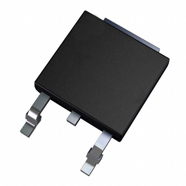
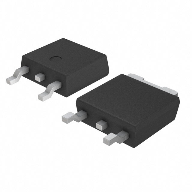
The IXTY2R4N50P is an N-Channel MOSFET manufactured by IXYS, rated for 500V drain-to-source voltage with 2.4A continuous drain current at 25°C. The device is housed in a TO-252AA (DPAK) surface mount package and delivers 55W maximum power dissipation. This part is classified as Obsolete and no longer in active production. Identifying equivalent and substitute components is necessary to maintain design continuity, ensure supply chain availability, and support ongoing manufacturing or repair operations for legacy systems.
Substiute Parts
Key Parameters
| Parameter | Value | Unit |
|---|---|---|
| Drain-to-Source Voltage (Vdss) | 500 | V |
| Continuous Drain Current (Id) @ 25°C | 2.4 | A (Tc) |
| On-State Resistance (Rds On) @ 500mA, 10V | 3.75 | Ohm |
| Gate Threshold Voltage (Vgs(th)) @ 25µA | 5.5 | V |
| Gate Charge (Qg) @ 10V | 6.1 | nC |
| Input Capacitance (Ciss) @ 25V | 240 | pF |
| Power Dissipation (Max) | 55 | W (Tc) |
| Operating Temperature Range | -55 to 150 | °C (TJ) |
| Package Type | TO-252-3 DPAK | Surface Mount |
| Gate Voltage (Max) | ±30 | V |
Substitute Part Grouping Explanation
Substitution of the IXTY2R4N50P is determined by strict alignment of the following critical electrical and mechanical parameters:
Primary Substitution Criteria:
- Drain-to-Source Voltage (Vdss): Must equal or exceed 500V
- Continuous Drain Current (Id): Must equal or exceed 2.4A at 25°C
- Package Type: Must be TO-252-3 DPAK or equivalent surface mount configuration
- Gate Voltage Rating (Vgs Max): Must support ±30V or greater
- Operating Temperature Range: Must encompass -55°C to 150°C
Secondary Compatibility Factors:
- On-State Resistance (Rds On): Lower values indicate improved performance; values within ±20% of original are acceptable
- Gate Charge (Qg): Lower values reduce switching losses; values within ±50% are acceptable
- Input Capacitance (Ciss): Lower values improve switching speed; values within ±50% are acceptable
- Power Dissipation: Must support thermal requirements of the application
Substitute parts are grouped into two categories:
Category A – Direct Voltage/Current Match (500V, ≥2.4A): Parts meeting or exceeding both voltage and current ratings with identical or superior electrical characteristics.
Category B – Voltage Elevation Substitutes (≥500V, ≥2.4A): Parts with higher voltage ratings that maintain current capability and are pin-compatible in TO-252 packaging.
Parameter Comparison
| Part Number | Manufacturer | Vdss (V) | Id @ 25°C (A) | Rds On (Ohm) | Vgs(th) (V) | Qg (nC) | Ciss (pF) | Pd Max (W) | Package | Status |
|---|---|---|---|---|---|---|---|---|---|---|
| IXTY2R4N50P | IXYS | 500 | 2.4 | 3.75 | 5.5 | 6.1 | 240 | 55 | TO-252AA | Obsolete |
| IXTY2N65X2 | IXYS | 650 | 2.0 | 2.3 | 5.0 | 4.3 | 180 | 55 | TO-252AA | Active |
| AOD3N50 | Alpha & Omega Semiconductor | 500 | 2.8 | 3.0 | 4.5 | 8.0 | 331 | 57 | TO-252 | Not For New Designs |
| IRFR310TRLPBF | Vishay Siliconix | 400 | 1.7 | 3.6 | 4.0 | 12.0 | 170 | 25 | DPAK | Active |
| IRFR420ATRLPBF | Vishay Siliconix | 500 | 3.3 | 3.0 | 4.5 | 17.0 | 340 | 83 | DPAK | Active |
| RFD3055LESM9A | onsemi | 60 | 11.0 | 0.107 | 3.0 | 11.3 | 350 | 38 | TO-252AA | Active |
| STD3NK50ZT4 | STMicroelectronics | 500 | 2.3 | 3.3 | 4.5 | 15.0 | 280 | 45 | DPAK | Active |
| STU4N52K3 | STMicroelectronics | 525 | 2.5 | 2.6 | 4.5 | 11.0 | 334 | 45 | I-PAK | Active |
Engineering Selection Recommendations
Recommended Primary Substitutes (Direct Replacement Candidates):
1. AOD3N50 (Alpha & Omega Semiconductor)
- Meets 500V voltage requirement with 2.8A current capability, exceeding the 2.4A specification
- Identical TO-252 DPAK package footprint
- Superior on-state resistance (3.0 Ohm vs. 3.75 Ohm) reduces conduction losses
- RoHS3 Compliant; REACH Unaffected
- Status: Not For New Designs (suitable for legacy system support and repair)
- Higher input capacitance (331 pF) requires gate drive circuit verification
2. STD3NK50ZT4 (STMicroelectronics)
- Meets 500V voltage requirement with 2.3A current capability, matching original specification
- TO-252 DPAK package compatibility confirmed
- Comparable on-state resistance (3.3 Ohm) with lower gate charge (15 nC vs. 6.1 nC)
- RoHS3 Compliant; REACH Unaffected; Active product status
- SuperMESH™ technology provides improved switching characteristics
- Higher gate charge requires verification of gate drive circuit capability
3. IRFR420ATRLPBF (Vishay Siliconix)
- Meets 500V voltage requirement with 3.3A current capability, exceeding original specification
- TO-252 DPAK package compatibility confirmed
- Superior on-state resistance (3.0 Ohm) and higher power dissipation (83W vs. 55W)
- RoHS3 Compliant; Active product status
- Significantly higher gate charge (17 nC) requires gate drive circuit assessment
- Suitable for applications requiring higher current margin
Alternative Voltage-Elevated Substitute:
4. IXTY2N65X2 (IXYS)
- Elevated voltage rating (650V) provides additional design margin
- Reduced current capability (2.0A) falls below 2.4A specification; not suitable for current-critical applications
- Superior on-state resistance (2.3 Ohm) and lower gate charge (4.3 nC)
- RoHS3 Compliant; Active product status
- Use only when application voltage headroom permits current derating
Not Recommended for Direct Substitution:
- IRFR310TRLPBF: 400V rating is insufficient for 500V application requirement
- RFD3055LESM9A: 60V rating is unsuitable; designed for low-voltage applications
- STU4N52K3: Through-hole I-PAK package incompatible with surface mount TO-252 footprint
Frequently Asked Questions (FAQ)
Q1: Can IRFR310TRLPBF replace IXTY2R4N50P in a 500V circuit?
A: No. IRFR310TRLPBF is rated for 400V maximum drain-to-source voltage. Using this part in a 500V application will result in device failure due to voltage overstress. The voltage rating must equal or exceed the circuit requirement.
Q2: Why does STU4N52K3 appear in the substitute list if it uses a different package?
A: STU4N52K3 is listed as a substitute in the provided input data; however, its I-PAK through-hole package is mechanically incompatible with the TO-252 surface mount footprint of IXTY2R4N50P. This part is not suitable for direct PCB replacement without redesign.
Q3: Is AOD3N50 acceptable for new designs?
A: AOD3N50 carries a "Not For New Designs" status, indicating the manufacturer has discontinued active support. It is suitable for legacy system repair and maintenance but should not be selected for new product development. For new designs, use STD3NK50ZT4 or IRFR420ATRLPBF.
Q4: What is the significance of gate charge (Qg) differences between substitutes?
A: Gate charge determines the energy required to switch the MOSFET on and off. Higher gate charge (e.g., IRFR420ATRLPBF at 17 nC vs. original 6.1 nC) requires a more robust gate drive circuit with higher current capability. Verify that the existing gate driver can supply sufficient current before substitution.
Q5: Can I use IXTY2N65X2 if my circuit operates below 500V?
A: Yes, if circuit voltage remains below 500V. IXTY2N65X2 provides additional voltage margin (650V rating) and superior on-state resistance (2.3 Ohm). However, its 2.0A current rating is lower than the original 2.4A specification. Verify that application current requirements do not exceed 2.0A continuous drain current.
Q6: What does "RoHS3 Compliant" mean for substitution?
A: RoHS3 Compliant indicates the part meets Restriction of Hazardous Substances Directive requirements, restricting lead, cadmium, mercury, and other hazardous materials. If your application or region requires RoHS compliance, select only RoHS3-compliant substitutes: AOD3N50, STD3NK50ZT4, IRFR420ATRLPBF, or IXTY2N65X2.
Q7: Are all substitute parts pin-compatible with IXTY2R4N50P?
A: All recommended substitutes (AOD3N50, STD3NK50ZT4, IRFR420ATRLPBF, IXTY2N65X2) use TO-252 DPAK or TO-252AA packaging with identical pin configuration (Gate, Drain, Source). Pin-for-pin replacement is possible without PCB modification. STU4N52K3 and RFD3055LESM9A use different packages and are not pin-compatible.
Q8: How do I verify thermal performance after substitution?
A: Compare power dissipation ratings and on-state resistance values. Lower Rds On reduces conduction losses. Verify that the substitute's maximum power dissipation (Pd Max) meets or exceeds your application's thermal requirements. Conduct thermal simulation or testing if application operates near maximum rated power.
Q9: What is the impact of input capacitance (Ciss) differences?
A: Input capacitance affects gate drive circuit performance and switching speed. Higher Ciss (e.g., AOD3N50 at 331 pF vs. original 240 pF) increases gate charge and switching losses. Verify that gate drive circuit bandwidth and current capability remain adequate. Lower Ciss (e.g., IXTY2N65X2 at 180 pF) improves switching speed and reduces losses.
Q10: Which substitute offers the best overall performance match?
A: STD3NK50ZT4 provides the closest electrical match: identical 500V rating, comparable 2.3A current (within specification), matching on-state resistance, and active product status with full manufacturer support. It is the recommended first choice for direct replacement in legacy system maintenance.
Alternative Parts

SJ6012L2TP
Littelfuse Inc.
6 Alternative Parts

JMK107BBJ476MA-RE
Taiyo Yuden
10 Alternative Parts

GMK107BBJ475MA-T
Taiyo Yuden
5 Alternative Parts
SJ6020N2ARP
Littelfuse Inc.
3 Alternative Parts
SJ6025R2ATP
Littelfuse Inc.
4 Alternative Parts

2474-05L
API Delevan Inc.
1 Alternative Parts

4590R-684K
API Delevan Inc.
1 Alternative Parts

CM6560R-334
API Delevan Inc.
1 Alternative Parts

CM6460-104
API Delevan Inc.
1 Alternative Parts

5526-12
API Delevan Inc.
1 Alternative Parts