


Request Quote
(Ships tomorrow)
IXTY1R4N60P N-Channel 600V 1.4A MOSFET Equivalent & Substitute Parts
Part Overview
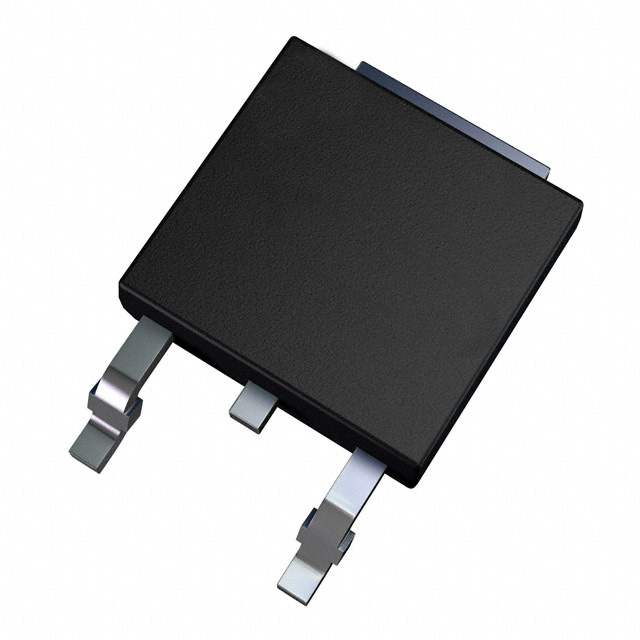
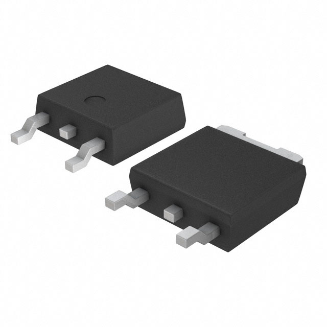
The IXTY1R4N60P is an N-Channel 600V MOSFET manufactured by IXYS in the PolarHV™ series, rated for 1.4A continuous drain current and 50W power dissipation in a surface mount TO-252AA package. This device is classified as obsolete, making identification of functionally equivalent alternatives necessary for ongoing production support, design updates, and component sourcing.
Substitute parts must maintain electrical compatibility across voltage ratings, current handling, gate drive characteristics, and thermal performance while accommodating the same or compatible package footprints.
Substiute Parts
Key Parameters
| Parameter | Value | Unit |
|---|---|---|
| FET Type | N-Channel | — |
| Drain to Source Voltage (Vdss) | 600 | V |
| Current - Continuous Drain (Id) @ 25°C | 1.4 | A (Tc) |
| Rds On (Max) @ Id, Vgs | 9 | Ohm @ 700mA, 10V |
| Vgs(th) (Max) @ Id | 5.5 | V @ 25µA |
| Gate Charge (Qg) (Max) @ Vgs | 5.2 | nC @ 10V |
| Vgs (Max) | ±30 | V |
| Input Capacitance (Ciss) (Max) @ Vds | 140 | pF @ 25V |
| Power Dissipation (Max) | 50 | W (Tc) |
| Operating Temperature | -55 to 150 | °C (TJ) |
| Mounting Type | Surface Mount | — |
| Package / Case | TO-252-3, DPAK (2 Leads + Tab), SC-63 | — |
| Moisture Sensitivity Level (MSL) | 1 (Unlimited) | — |
Substitute Part Grouping Explanation
Substitution eligibility is determined by the following electrical and mechanical criteria:
Mandatory Matching Parameters:
- Drain to Source Voltage (Vdss): 600V
- FET Type: N-Channel
- Technology: MOSFET (Metal Oxide)
- Mounting Type: Surface Mount
- Package / Case: TO-252-3, DPAK (2 Leads + Tab), SC-63
- Gate Drive Voltage (Vgs Max): ±30V
- Operating Temperature Range: -55°C to 150°C minimum
Functional Compatibility Parameters:
- Current - Continuous Drain (Id) @ 25°C: 1.4A or greater
- Rds On (Max) @ 10V: 9 Ohm or lower
- Power Dissipation (Max): 50W or greater
- Gate Charge (Qg): 5.2 nC or lower (preferred for gate drive efficiency)
- Input Capacitance (Ciss): 140 pF or lower (preferred for switching speed)
All four substitute parts meet the mandatory matching parameters. Functional compatibility varies based on current rating, on-resistance, and power dissipation specifications.
Parameter Comparison
| Parameter | IXTY1R4N60P (Main) | AOD1N60 | FQD1N60CTM | IRFR1N60ATRPBF | STD1HN60K3 |
|---|---|---|---|---|---|
| Manufacturer | IXYS | Alpha & Omega Semiconductor Inc. | Fairchild Semiconductor | Vishay Siliconix | STMicroelectronics |
| Drain to Source Voltage (Vdss) | 600 V | 600 V | 600 V | 600 V | 600 V |
| Current - Continuous Drain (Id) @ 25°C | 1.4 A (Tc) | 1.3 A (Tc) | 1 A (Tc) | 1.4 A (Tc) | 1.2 A (Tc) |
| Rds On (Max) @ 10V | 9 Ohm @ 700mA | 9 Ohm @ 650mA | 11.5 Ohm @ 500mA | 7 Ohm @ 840mA | 8 Ohm @ 600mA |
| Vgs(th) (Max) @ Id | 5.5 V @ 25µA | 4.5 V @ 250µA | 4 V @ 250µA | 4 V @ 250µA | 4.5 V @ 50µA |
| Gate Charge (Qg) (Max) @ 10V | 5.2 nC | 8 nC | 6.2 nC | 14 nC | 9.5 nC |
| Vgs (Max) | ±30 V | ±30 V | ±30 V | ±30 V | ±30 V |
| Input Capacitance (Ciss) (Max) @ Vds | 140 pF @ 25V | 160 pF @ 25V | 170 pF @ 25V | 229 pF @ 25V | 140 pF @ 50V |
| Power Dissipation (Max) | 50 W (Tc) | 45 W (Tc) | 28 W (Tc) | 36 W (Tc) | 27 W (Tc) |
| Operating Temperature | -55 to 150 °C (TJ) | -50 to 150 °C (TJ) | -55 to 150 °C (TJ) | -55 to 150 °C (TJ) | -55 to 150 °C (TJ) |
| Package / Case | TO-252-3, DPAK | TO-252-3, DPAK | TO-252-3, DPAK | TO-252-3, DPAK | TO-252-3, DPAK |
| Product Status | Obsolete | Not For New Designs | Active | Active | Active |
| RoHS Status | — | ROHS3 Compliant | — | ROHS3 Compliant | ROHS3 Compliant |
| REACH Status | — | REACH Unaffected | — | REACH Affected | REACH Unaffected |
Engineering Selection Recommendations
IRFR1N60ATRPBF (Vishay Siliconix)
This substitute provides the closest electrical match to the IXTY1R4N60P. It maintains identical 600V/1.4A ratings and delivers superior on-resistance performance (7 Ohm vs. 9 Ohm), enabling lower conduction losses. The device is classified as Active with ROHS3 compliance. The higher gate charge (14 nC) and input capacitance (229 pF) require verification against gate driver specifications in applications with tight switching frequency constraints. REACH status is listed as Affected, requiring compliance confirmation for regulated markets.
STD1HN60K3 (STMicroelectronics)
This substitute operates within acceptable electrical parameters with 1.2A continuous drain current and 8 Ohm on-resistance. The SuperMESH3™ technology provides thermal efficiency with 27W power dissipation rating. The device is Active with ROHS3 and REACH Unaffected certifications, supporting unrestricted deployment in regulated applications. The lower current rating (1.2A vs. 1.4A) requires thermal margin verification in high-current applications.
AOD1N60 (Alpha & Omega Semiconductor Inc.)
This substitute meets electrical requirements with 1.3A continuous drain current and 9 Ohm on-resistance matching the main part specification. The device is classified as Not For New Designs, limiting its suitability for new product development. ROHS3 compliance and REACH Unaffected status support existing production environments. The -50°C minimum operating temperature is 5°C higher than the main part, requiring thermal range verification for applications below -50°C.
FQD1N60CTM (Fairchild Semiconductor)
This substitute is classified as Active with the lowest power dissipation rating (28W) among alternatives. The 1A continuous drain current and 11.5 Ohm on-resistance represent significant derating from the main part specification, limiting applicability to lower-current designs. This device is suitable only for applications where the reduced current and power ratings align with circuit requirements.
Frequently Asked Questions (FAQ)
Q: Can IRFR1N60ATRPBF directly replace IXTY1R4N60P without circuit modifications?
A: IRFR1N60ATRPBF is electrically compatible at the package and voltage level. However, the higher gate charge (14 nC vs. 5.2 nC) and input capacitance (229 pF vs. 140 pF) may require gate driver current verification. If the existing gate driver is current-limited, switching frequency or rise/fall times may be affected. PCB layout and thermal management should be re-evaluated for the different power dissipation profile (36W vs. 50W).
Q: Is AOD1N60 suitable for new product designs?
A: AOD1N60 is classified as Not For New Designs. While electrically compatible, it is intended for legacy production support only. For new designs, IRFR1N60ATRPBF, STD1HN60K3, or FQD1N60CTM are preferred based on Active product status.
Q: What is the impact of lower current ratings in STD1HN60K3 and FQD1N60CTM?
A: STD1HN60K3 (1.2A) and FQD1N60CTM (1A) have reduced continuous drain current compared to the main part (1.4A). In applications operating near the 1.4A limit, these devices will reach thermal limits sooner. Thermal analysis must confirm that the reduced power dissipation ratings (27W and 28W respectively) provide adequate margin for the intended duty cycle.
Q: Are all substitute parts RoHS and REACH compliant?
A: IRFR1N60ATRPBF, STD1HN60K3, and AOD1N60 are ROHS3 compliant. IRFR1N60ATRPBF is listed as REACH Affected, requiring compliance verification for regulated markets. STD1HN60K3 and AOD1N60 are REACH Unaffected. FQD1N60CTM compliance status is not provided in the available data.
Q: Can these substitutes be used interchangeably in the same PCB layout?
A: All substitute parts use the TO-252-3 DPAK package with identical pin configuration and footprint. PCB layout compatibility is confirmed. However, thermal management may require adjustment due to different power dissipation ratings. Verify thermal pad sizing and copper area for heat dissipation in high-power applications.
Q: Which substitute offers the best thermal performance?
A: IRFR1N60ATRPBF delivers the lowest on-resistance (7 Ohm), reducing conduction losses and heat generation. However, its 36W power dissipation rating is lower than the main part (50W). STD1HN60K3 provides balanced performance with 8 Ohm on-resistance and 27W dissipation. For applications requiring maximum thermal headroom, the main part specification (50W) should be retained if available.
Q: What is the significance of gate charge differences?
A: Gate charge (Qg) determines the energy required to switch the MOSFET on and off. The main part specifies 5.2 nC, while IRFR1N60ATRPBF requires 14 nC. Higher gate charge increases switching losses and may require higher gate driver current. In high-frequency applications, this can impact efficiency and thermal performance. Verify gate driver specifications before substitution.
Q: Are there temperature range limitations with any substitute?
A: AOD1N60 specifies -50°C to 150°C, compared to -55°C to 150°C for the main part and other substitutes. Applications requiring operation below -50°C must use IRFR1N60ATRPBF, FQD1N60CTM, or STD1HN60K3.
Alternative Parts

SJ6012L2TP
Littelfuse Inc.
6 Alternative Parts

JMK107BBJ476MA-RE
Taiyo Yuden
10 Alternative Parts

GMK107BBJ475MA-T
Taiyo Yuden
5 Alternative Parts
SJ6020N2ARP
Littelfuse Inc.
3 Alternative Parts
SJ6025R2ATP
Littelfuse Inc.
4 Alternative Parts

2474-05L
API Delevan Inc.
1 Alternative Parts

4590R-684K
API Delevan Inc.
1 Alternative Parts

CM6560R-334
API Delevan Inc.
1 Alternative Parts

CM6460-104
API Delevan Inc.
1 Alternative Parts

5526-12
API Delevan Inc.
1 Alternative Parts