


Request Quote
(Ships tomorrow)
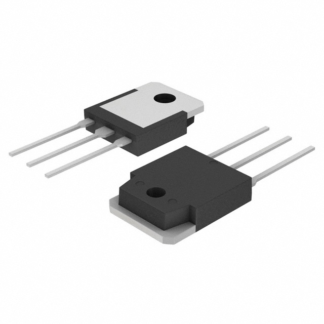
IXTQ18N60P N-Channel 600V 18A MOSFET Equivalent & Substitute Parts
Part Overview
The IXTQ18N60P is an N-Channel MOSFET manufactured by IXYS, rated for 600V drain-to-source voltage with 18A continuous drain current at 25°C. This device is housed in a TO-3P package and is designed for through-hole mounting applications requiring high-voltage switching capability. The part is classified as Active product status with full RoHS3 compliance and REACH unaffected designation.
Substitute parts become necessary when the IXTQ18N60P reaches end-of-life status, when inventory constraints occur, or when application requirements demand alternative electrical or thermal performance characteristics within the same voltage class and technology platform.
Substiute Parts
Key Parameters
| Parameter | Value | Unit |
|---|---|---|
| Drain-to-Source Voltage (Vdss) | 600 | V |
| Continuous Drain Current (Id) @ 25°C | 18 | A |
| RDS(on) Max @ 9A, 10V | 420 | mOhm |
| Gate Threshold Voltage (Vgs(th)) @ 250µA | 5.5 | V |
| Power Dissipation (Max) | 360 | W |
| Operating Temperature Range | -55 to 150 | °C |
| Package Type | TO-3P | — |
| Mounting Type | Through Hole | — |
Substitute Part Grouping Explanation
Substitution eligibility for the IXTQ18N60P is determined by the following critical parameters:
Mandatory Matching Criteria:
- Drain-to-Source Voltage (Vdss): 600V (exact match required)
- FET Type: N-Channel
- Technology: MOSFET (Metal Oxide)
- Operating Temperature Range: -55°C to 150°C (minimum requirement)
Flexible Parameters (Application-Dependent):
- Continuous Drain Current (Id): Substitute must equal or exceed 18A
- RDS(on): Substitute must equal or be lower than 420mOhm at specified conditions
- Power Dissipation: Substitute must equal or exceed 360W
- Package Type: Through-hole packages (TO-3P, TO-247-3, or equivalent)
The FCH041N60F qualifies as a substitute based on matching voltage class (600V), FET type (N-Channel), technology (MOSFET), and operating temperature range. The substitute exhibits superior current handling (76A vs. 18A) and lower on-resistance (41mOhm vs. 420mOhm), making it electrically compatible for applications where the IXTQ18N60P is specified.
Parameter Comparison
| Parameter | IXTQ18N60P (Main) | FCH041N60F (Substitute) | Unit |
|---|---|---|---|
| Manufacturer | IXYS | onsemi | — |
| FET Type | N-Channel | N-Channel | — |
| Technology | MOSFET (Metal Oxide) | MOSFET (Metal Oxide) | — |
| Drain-to-Source Voltage (Vdss) | 600 | 600 | V |
| Continuous Drain Current (Id) @ 25°C | 18 | 76 | A |
| RDS(on) Max @ Specified Conditions | 420 @ 9A, 10V | 41 @ 38A, 10V | mOhm |
| Gate Threshold Voltage (Vgs(th)) @ 250µA | 5.5 | 5.0 | V |
| Gate Charge (Qg) @ 10V | 49 | 360 | nC |
| Power Dissipation (Max) | 360 | 595 | W |
| Operating Temperature Range | -55 to 150 | -55 to 150 | °C |
| Package Type | TO-3P | TO-247-3 | — |
| Mounting Type | Through Hole | Through Hole | — |
| RoHS Status | ROHS3 Compliant | ROHS3 Compliant | — |
| REACH Status | REACH Unaffected | REACH Unaffected | — |
| Product Status | Active | Not For New Designs | — |
Engineering Selection Recommendations
IXTQ18N60P Selection: The IXTQ18N60P is the primary choice for new designs. This part carries Active product status, indicating full manufacturer support and continued availability. It maintains RoHS3 compliance and REACH unaffected designation, meeting current regulatory requirements. The device is suitable for applications requiring 600V switching capability with moderate current demands up to 18A.
FCH041N60F Selection: The FCH041N60F is available as a substitute for existing applications where the IXTQ18N60P is specified or where inventory constraints exist. This part is classified as Not For New Designs, indicating it is maintained for legacy support only. The substitute provides superior electrical performance with 76A continuous drain current and significantly lower on-resistance (41mOhm), resulting in reduced power dissipation and improved thermal efficiency. Both parts maintain identical voltage ratings (600V), operating temperature ranges (-55°C to 150°C), and regulatory compliance (RoHS3, REACH unaffected).
Package Consideration: The primary difference between these parts is the package type. The IXTQ18N60P uses TO-3P packaging, while the FCH041N60F uses TO-247-3 packaging. Both are through-hole mount devices. PCB layout modifications may be required when transitioning between these packages due to different pin configurations and thermal pad geometries.
Frequently Asked Questions (FAQ)
Q: Can the FCH041N60F directly replace the IXTQ18N60P in existing circuit designs?
A: Electrical substitution is valid based on matching voltage class (600V), FET type (N-Channel), and operating temperature range. However, package differences (TO-3P vs. TO-247-3) require PCB layout modifications. Pin assignments and thermal pad locations differ between these packages, necessitating circuit board redesign.
Q: What are the key electrical advantages of the FCH041N60F over the IXTQ18N60P?
A: The FCH041N60F provides four times the continuous drain current (76A vs. 18A) and approximately 10 times lower on-resistance (41mOhm vs. 420mOhm). These characteristics result in lower power dissipation and improved thermal performance in high-current applications.
Q: Why is the FCH041N60F marked as "Not For New Designs"?
A: This designation indicates the part is in legacy support phase. The manufacturer maintains production for existing customer applications but does not recommend it for new product development. New designs should prioritize the IXTQ18N60P or other actively supported alternatives.
Q: Are both parts compliant with current environmental and regulatory standards?
A: Yes. Both the IXTQ18N60P and FCH041N60F are RoHS3 compliant and REACH unaffected, meeting current environmental regulations for electronic components.
Q: What is the significance of the different gate charge values (49 nC vs. 360 nC)?
A: Gate charge directly affects gate drive circuit requirements and switching speed. The IXTQ18N60P requires less gate charge (49 nC), enabling faster switching with lower drive power. The FCH041N60F requires higher gate charge (360 nC) due to its larger die and higher current capability, necessitating more robust gate drive circuitry.
Q: Can the IXTQ18N60P be used in applications originally designed for the FCH041N60F?
A: No. The IXTQ18N60P has lower current rating (18A vs. 76A) and higher on-resistance (420mOhm vs. 41mOhm). Using it in applications designed for the FCH041N60F would result in inadequate current handling and excessive power dissipation, potentially causing device failure or thermal shutdown.
Q: What thermal considerations apply when substituting between these parts?
A: The FCH041N60F dissipates more power (595W vs. 360W maximum) and has lower on-resistance, resulting in reduced junction temperature rise under identical load conditions. However, the TO-247-3 package may have different thermal resistance characteristics compared to TO-3P. Thermal analysis specific to the application and PCB design is necessary to ensure adequate heat dissipation.
Alternative Parts

SJ6012L2TP
Littelfuse Inc.
6 Alternative Parts

JMK107BBJ476MA-RE
Taiyo Yuden
10 Alternative Parts

GMK107BBJ475MA-T
Taiyo Yuden
5 Alternative Parts
SJ6020N2ARP
Littelfuse Inc.
3 Alternative Parts
SJ6025R2ATP
Littelfuse Inc.
4 Alternative Parts

2474-05L
API Delevan Inc.
1 Alternative Parts

4590R-684K
API Delevan Inc.
1 Alternative Parts

CM6560R-334
API Delevan Inc.
1 Alternative Parts

CM6460-104
API Delevan Inc.
1 Alternative Parts

5526-12
API Delevan Inc.
1 Alternative Parts