


Request Quote
(Ships tomorrow)
IXTP8N65X2M Equivalent & Substitute Parts
Part Overview
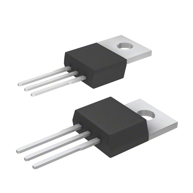
The IXTP8N65X2M is an N-Channel MOSFET manufactured by IXYS in the Ultra X2 series, rated for 650V drain-to-source voltage with 4A continuous drain current at 25°C. This device is packaged in TO-220-3 through-hole configuration and is designed for high-voltage switching applications. The part is currently in active production status with RoHS3 compliance and unlimited moisture sensitivity level (MSL 1).
Substitute parts are necessary when the IXTP8N65X2M becomes unavailable, when alternative sourcing is required for supply chain optimization, or when design requirements permit operation within the electrical and mechanical parameters of equivalent devices. Substitutes must maintain compatibility with TO-220-3 through-hole mounting and operate within the specified voltage and current ranges of the original application.
Substiute Parts
Key Parameters
| Parameter | Value | Unit |
|---|---|---|
| Drain to Source Voltage (Vdss) | 650 | V |
| Continuous Drain Current (Id) @ 25°C | 4 | A (Tc) |
| Rds On (Max) @ 4A, 10V | 550 | mOhm |
| Gate Threshold Voltage (Vgs(th)) @ 250µA | 5 | V |
| Gate Charge (Qg) @ 10V | 12 | nC |
| Power Dissipation (Max) | 32 | W (Tc) |
| Operating Temperature Range | -55 to 150 | °C (TJ) |
| Package Type | TO-220-3 | Through Hole |
| Product Status | Active | — |
Substitute Part Grouping Explanation
Substitution of the IXTP8N65X2M is determined by the following critical parameters:
Voltage Rating Compatibility: The main part operates at 650V Vdss. Substitute parts must have equal or greater voltage ratings to ensure safe operation in the same circuit topology. A lower voltage rating creates risk of device failure under normal operating conditions.
Current Rating Compatibility: The main part is rated for 4A continuous drain current. Substitute parts with equal or higher current ratings can be used without derating. Parts with lower current ratings require circuit redesign and thermal analysis.
Package and Mounting: All substitute parts must use TO-220-3 through-hole packaging to maintain mechanical compatibility with existing PCB layouts and thermal management solutions.
Thermal Characteristics: Operating temperature range (-55°C to 150°C) must be maintained across all substitutes to ensure reliability across the full application temperature envelope.
Drive Voltage: All parts operate at 10V drive voltage for Rds On specification, ensuring gate driver compatibility.
The two substitute parts identified—FCP600N60Z and STP10NM60ND—meet these core substitution criteria with the following considerations:
FCP600N60Z (Fairchild Semiconductor): 600V rating (50V lower than main part), 7.4A continuous current (higher than main part), 89W power dissipation, TO-220-3 package, active product status.
STP10NM60ND (STMicroelectronics): 600V rating (50V lower than main part), 8A continuous current (higher than main part), 70W power dissipation, TO-220-3 package, obsolete product status.
Parameter Comparison
| Parameter | IXTP8N65X2M (Main) | FCP600N60Z (Substitute) | STP10NM60ND (Substitute) |
|---|---|---|---|
| Manufacturer | IXYS | Fairchild Semiconductor | STMicroelectronics |
| Series | Ultra X2 | SuperFET® II | FDmesh™ II |
| Drain to Source Voltage (Vdss) | 650 V | 600 V | 600 V |
| Continuous Drain Current (Id) @ 25°C | 4 A (Tc) | 7.4 A (Tc) | 8 A (Tc) |
| Rds On (Max) @ 10V | 550 mOhm @ 4A | 600 mOhm @ 3.7A | 600 mOhm @ 4A |
| Gate Threshold Voltage (Vgs(th)) @ 250µA | 5 V | 3.5 V | 5 V |
| Gate Charge (Qg) @ 10V | 12 nC | 26 nC | 20 nC |
| Maximum Vgs | ±30 V | ±20 V | ±25 V |
| Input Capacitance (Ciss) @ 25V | 800 pF | 1120 pF @ 25V | 577 pF @ 50V |
| Power Dissipation (Max) | 32 W (Tc) | 89 W (Tc) | 70 W (Tc) |
| Operating Temperature Range | -55 to 150 °C (TJ) | -55 to 150 °C (TJ) | -55 to 150 °C (TJ) |
| Package Type | TO-220-3 | TO-220-3 | TO-220-3 |
| Product Status | Active | Active | Obsolete |
| RoHS3 Compliance | Yes | Not specified | Yes |
Engineering Selection Recommendations
FCP600N60Z Selection Criteria:
The FCP600N60Z is suitable for applications where the 50V reduction in Vdss (from 650V to 600V) is acceptable within the circuit design margin. This part offers higher continuous current capability (7.4A versus 4A) and greater power dissipation capacity (89W versus 32W), making it appropriate for designs with thermal headroom or higher current requirements. The part maintains active product status, ensuring long-term availability and supply chain stability. RoHS3 compliance status is not specified in the provided data; verification against specific regulatory requirements is necessary before selection.
STP10NM60ND Selection Criteria:
The STP10NM60ND carries obsolete product status, indicating discontinued manufacturing and limited future availability. While the part currently has inventory (1210 pcs), this substitute should be selected only when FCP600N60Z is unavailable and existing stock is accessible. The 600V Vdss rating and 8A current capability provide functional equivalence for the main part's 4A requirement. RoHS3 compliance is confirmed. The higher gate charge (20 nC versus 12 nC) may require gate driver adjustment in timing-sensitive applications.
Primary Recommendation:
For new designs and long-term production, FCP600N60Z is the preferred substitute due to active product status and superior thermal characteristics. For existing inventory management or legacy system support, STP10NM60ND remains functionally compatible within the specified parameter ranges.
Frequently Asked Questions (FAQ)
Q: Can the FCP600N60Z be used as a direct replacement for the IXTP8N65X2M?
A: The FCP600N60Z is functionally compatible for applications where the circuit design margin accommodates a 50V reduction in maximum drain-to-source voltage (from 650V to 600V). The higher current rating (7.4A) and power dissipation (89W) provide additional design flexibility. Gate threshold voltage differs (3.5V versus 5V), which may affect gate driver timing. Verification against specific application voltage stress conditions is required before implementation.
Q: What is the impact of the lower Vdss rating on circuit reliability?
A: Both substitute parts operate at 600V Vdss compared to the main part's 650V rating. This 50V difference reduces the maximum voltage stress margin by approximately 7.7%. In applications operating near the 600V threshold, this reduction may be acceptable. In applications with voltage transients or overshoot conditions, the lower rating increases risk of device failure. Circuit analysis of peak voltage conditions is necessary to confirm compatibility.
Q: Are there differences in gate drive requirements between these parts?
A: All three parts operate at 10V drive voltage for Rds On specification. However, gate threshold voltages differ: FCP600N60Z at 3.5V versus IXTP8N65X2M and STP10NM60ND at 5V. Gate charge also varies: IXTP8N65X2M at 12 nC, STP10NM60ND at 20 nC, and FCP600N60Z at 26 nC. These differences may require adjustment to gate driver timing and current capability, particularly in high-frequency switching applications.
Q: Why is the STP10NM60ND marked as obsolete?
A: The STP10NM60ND is listed with obsolete product status, indicating STMicroelectronics has discontinued active manufacturing. While inventory remains available (1210 pcs), future supply cannot be guaranteed. This part should be used only when FCP600N60Z is unavailable or when existing stock is being consumed in legacy system support.
Q: Can these parts be used interchangeably in the same PCB layout?
A: Yes. All three parts use TO-220-3 through-hole packaging with identical pin configuration and mechanical dimensions. PCB layout and thermal management solutions designed for the IXTP8N65X2M are directly compatible with both substitute parts without modification.
Q: What compliance certifications should be verified before selection?
A: The IXTP8N65X2M and STP10NM60ND are confirmed RoHS3 compliant. The FCP600N60Z RoHS3 compliance status is not specified in the provided data. All three parts carry EAR99 ECCN classification. Specific regulatory requirements for your application (automotive, industrial, medical) must be verified against manufacturer documentation before final part selection.
Q: How do the power dissipation ratings affect thermal design?
A: The IXTP8N65X2M is rated for 32W maximum power dissipation, while FCP600N60Z is rated for 89W and STP10NM60ND for 70W. Higher power dissipation ratings indicate greater thermal capacity. If the original design operates near the 32W limit, substitution with a higher-rated part provides thermal margin. Conversely, if thermal management is marginal, the higher dissipation capability of the substitute parts may improve system reliability.
Alternative Parts

SJ6012L2TP
Littelfuse Inc.
6 Alternative Parts

JMK107BBJ476MA-RE
Taiyo Yuden
10 Alternative Parts

GMK107BBJ475MA-T
Taiyo Yuden
5 Alternative Parts
SJ6020N2ARP
Littelfuse Inc.
3 Alternative Parts
SJ6025R2ATP
Littelfuse Inc.
4 Alternative Parts

2474-05L
API Delevan Inc.
1 Alternative Parts

4590R-684K
API Delevan Inc.
1 Alternative Parts

CM6560R-334
API Delevan Inc.
1 Alternative Parts

CM6460-104
API Delevan Inc.
1 Alternative Parts

5526-12
API Delevan Inc.
1 Alternative Parts