


Request Quote
(Ships tomorrow)
IXTP200N055T2 Equivalent & Substitute Parts
Part Overview
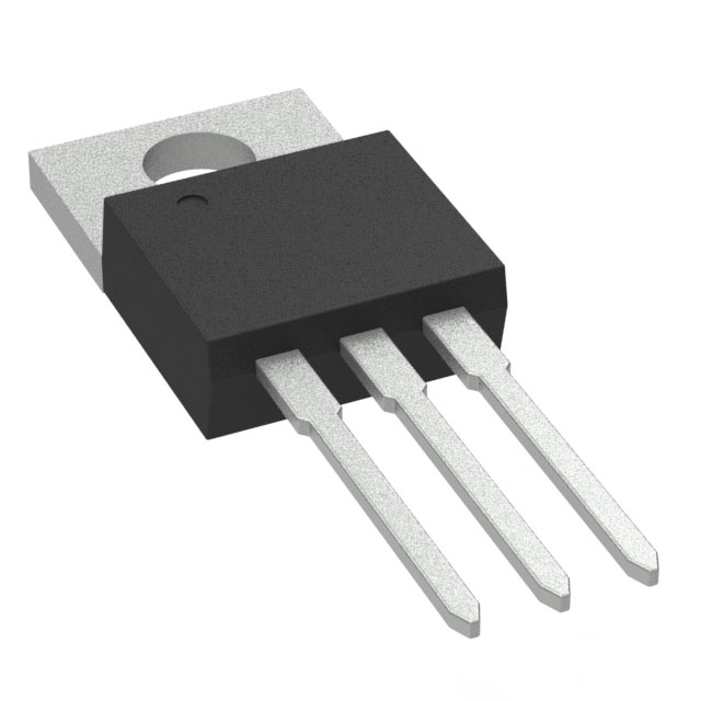
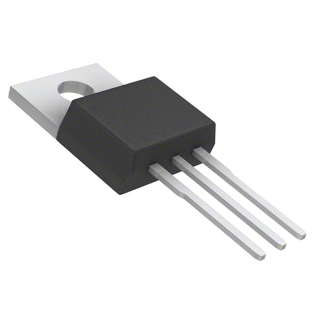
The IXTP200N055T2 is an N-Channel MOSFET manufactured by IXYS in the TrenchT2™ series. This through-hole TO-220-3 package device is rated for 55V drain-to-source voltage and 200A continuous drain current at 25°C, with a maximum power dissipation of 360W. The part is currently active in production and RoHS3 compliant.
Substitute parts are identified when equivalent electrical and mechanical parameters are available from alternative manufacturers. Substitution becomes necessary when the primary part reaches end-of-life status, inventory constraints occur, or design flexibility across multiple suppliers is required.
Substiute Parts
Key Parameters
| Parameter | Value | Unit |
|---|---|---|
| Drain to Source Voltage (Vdss) | 55 | V |
| Continuous Drain Current (Id) @ 25°C | 200 | A |
| On-State Resistance (Rds On) @ 50A, 10V | 4.2 | mOhm |
| Gate Threshold Voltage (Vgs(th)) @ 250µA | 4 | V |
| Gate Charge (Qg) @ 10V | 109 | nC |
| Input Capacitance (Ciss) @ 25V | 6800 | pF |
| Power Dissipation (Max) | 360 | W |
| Operating Temperature Range | -55 to 175 | °C |
| Package Type | TO-220-3 | — |
| Mounting Type | Through Hole | — |
Substitute Part Grouping Explanation
Substitution logic for the IXTP200N055T2 is based on the following critical parameters:
Electrical Compatibility Criteria:
- Drain-to-source voltage (Vdss) must be equal to or greater than 55V
- Continuous drain current (Id) must be equal to or greater than 200A at 25°C
- On-state resistance (Rds On) must be comparable to enable equivalent power dissipation performance
- Gate threshold voltage (Vgs(th)) and gate charge (Qg) must fall within acceptable ranges to ensure gate drive compatibility
- Maximum gate voltage (Vgs Max) must be ±20V to match drive circuit specifications
- Operating temperature range must encompass -55°C to 175°C
Mechanical Compatibility Criteria:
- Package type must be TO-220-3 or TO-220AB (mechanically compatible through-hole packages)
- Mounting type must be through-hole
Compliance Criteria:
- RoHS3 compliance required
- REACH unaffected status required
- Active or recently active product status preferred
Substitute parts identified in this reference meet these criteria with allowable parameter variations that maintain functional equivalence within standard circuit design tolerances.
Parameter Comparison
| Parameter | IXTP200N055T2 | CSD18532KCS | IRFB3207ZPBF | IRFB3306PBF | PSMN4R2-60PLQ |
|---|---|---|---|---|---|
| Manufacturer | IXYS | Texas Instruments | Infineon Technologies | Infineon Technologies | Nexperia USA Inc. |
| Vdss (V) | 55 | 60 | 75 | 60 | 60 |
| Id @ 25°C (A) | 200 | 100 | 120 | 120 | 130 |
| Rds On (mOhm) | 4.2 @ 50A, 10V | 4.2 @ 100A, 10V | 4.1 @ 75A, 10V | 4.2 @ 75A, 10V | 3.9 @ 25A, 10V |
| Vgs(th) (V) | 4 @ 250µA | 2.2 @ 250µA | 4 @ 150µA | 4 @ 150µA | 2.1 @ 1mA |
| Qg @ 10V (nC) | 109 | 53 | 170 | 120 | 151 |
| Ciss @ Vds (pF) | 6800 @ 25V | 4680 @ 30V | 6920 @ 50V | 4520 @ 50V | 8533 @ 25V |
| Power Dissipation (W) | 360 | 250 | 300 | 230 | 263 |
| Operating Temperature (°C) | -55 to 175 | -55 to 175 | -55 to 175 | -55 to 175 | -55 to 175 |
| Package | TO-220-3 | TO-220-3 | TO-220AB | TO-220AB | TO-220AB |
| Product Status | Active | Active | Active | Active | Obsolete |
| RoHS3 Compliance | Yes | Yes | Yes | Yes | Yes |
| REACH Status | Unaffected | Unaffected | Unaffected | Unaffected | Unaffected |
Engineering Selection Recommendations
Primary Consideration: Current Rating
The IXTP200N055T2 is rated for 200A continuous drain current. All listed substitute parts have lower current ratings (100A to 130A). This represents a significant parameter deviation. Substitution is only valid in applications where the actual circuit current demand does not exceed the substitute part's rating.
CSD18532KCS (Texas Instruments NexFET™)
Status: Active. This part offers the lowest gate charge (53 nC) and reduced input capacitance (4680 pF), resulting in faster switching characteristics. However, the 100A current rating is substantially lower than the primary part. Suitable only for applications with maximum current requirements below 100A. RoHS3 compliant and REACH unaffected.
IRFB3207ZPBF (Infineon Technologies HEXFET®)
Status: Active. This part provides the highest voltage rating (75V) among substitutes, offering additional design margin. The 120A current rating remains below the primary part specification. Gate charge of 170 nC is higher than the primary part, requiring verification of gate drive circuit capability. RoHS3 compliant and REACH unaffected.
IRFB3306PBF (Infineon Technologies HEXFET®)
Status: Active. This part matches the 60V voltage class and provides 120A current rating. Gate charge (120 nC) is comparable to the primary part. Power dissipation rating of 230W is lower than the primary part's 360W. Suitable for applications with current requirements up to 120A and thermal management compatible with 230W dissipation. RoHS3 compliant and REACH unaffected.
PSMN4R2-60PLQ (Nexperia USA Inc.)
Status: Obsolete. Although this part offers the highest current rating among substitutes (130A) and lowest on-state resistance (3.9 mOhm), its obsolete status makes it unsuitable for new designs or long-term production. Existing inventory may be available but future sourcing is not guaranteed. Use only in legacy system maintenance scenarios.
Recommendation Summary
For applications requiring the full 200A current capability of the IXTP200N055T2, no direct substitute exists among the listed parts. For applications with reduced current requirements (≤130A), select based on voltage margin requirements and thermal dissipation constraints. All active substitutes maintain compliance with RoHS3 and REACH requirements.
Frequently Asked Questions (FAQ)
Q: Can the CSD18532KCS replace the IXTP200N055T2 in all applications?
A: No. The CSD18532KCS is rated for 100A continuous drain current, compared to the IXTP200N055T2's 200A rating. Substitution is valid only in circuits where the maximum continuous drain current does not exceed 100A. Exceeding this limit will cause device failure or thermal shutdown.
Q: What is the significance of the gate charge (Qg) difference between these parts?
A: Gate charge affects switching speed and gate drive circuit power consumption. The IXTP200N055T2 has a gate charge of 109 nC. The CSD18532KCS (53 nC) will switch faster with lower drive power, while the IRFB3207ZPBF (170 nC) will switch slower and require higher drive power. Gate drive circuits must be verified to handle the substitute part's gate charge specification.
Q: Are TO-220-3 and TO-220AB packages mechanically interchangeable?
A: TO-220-3 and TO-220AB are mechanically compatible through-hole packages with identical pin spacing and mounting hole patterns. Both fit standard TO-220 PCB footprints and heat sink mounting hardware. No mechanical redesign is required when substituting between these package types.
Q: Why is the PSMN4R2-60PLQ listed as obsolete?
A: The PSMN4R2-60PLQ has reached end-of-life status and is no longer in active production. While existing inventory may be available from distributors, future availability is not guaranteed. New designs should not incorporate obsolete parts. This part is listed for reference only in legacy system maintenance scenarios.
Q: What does RoHS3 compliance mean for substitution?
A: RoHS3 compliance indicates the part meets Restriction of Hazardous Substances Directive requirements, restricting lead, cadmium, mercury, and other hazardous materials. All listed substitute parts are RoHS3 compliant, ensuring regulatory equivalence for applications subject to RoHS requirements.
Q: How do I determine if a substitute part is suitable for my application?
A: Compare the substitute part's continuous drain current (Id) rating against your circuit's maximum sustained current. Verify the drain-to-source voltage (Vdss) rating exceeds your circuit's maximum voltage. Confirm the operating temperature range encompasses your application's thermal environment. Validate gate drive circuit compatibility with the substitute part's gate charge and threshold voltage specifications.
Q: What is the impact of lower power dissipation ratings in substitute parts?
A: Power dissipation rating indicates the maximum heat the device can safely dissipate under specified conditions. Substitute parts with lower power dissipation ratings (e.g., IRFB3306PBF at 230W versus IXTP200N055T2 at 360W) require more effective thermal management. Verify that your heat sink and PCB thermal design can maintain junction temperature within the -55°C to 175°C operating range at the substitute part's lower dissipation limit.
Q: Can I use a substitute part with higher voltage rating (Vdss) than the primary part?
A: Yes. A substitute part with higher Vdss rating (e.g., IRFB3207ZPBF at 75V versus IXTP200N055T2 at 55V) provides additional voltage margin and is electrically compatible. Higher voltage ratings do not create compatibility issues in circuits designed for lower voltages. However, verify that other electrical parameters (current, gate charge, capacitance) remain within acceptable ranges for your gate drive circuit.
Alternative Parts

SJ6012L2TP
Littelfuse Inc.
6 Alternative Parts

JMK107BBJ476MA-RE
Taiyo Yuden
10 Alternative Parts

GMK107BBJ475MA-T
Taiyo Yuden
5 Alternative Parts
SJ6020N2ARP
Littelfuse Inc.
3 Alternative Parts
SJ6025R2ATP
Littelfuse Inc.
4 Alternative Parts

2474-05L
API Delevan Inc.
1 Alternative Parts

4590R-684K
API Delevan Inc.
1 Alternative Parts

CM6560R-334
API Delevan Inc.
1 Alternative Parts

CM6460-104
API Delevan Inc.
1 Alternative Parts

5526-12
API Delevan Inc.
1 Alternative Parts