


Request Quote
(Ships tomorrow)
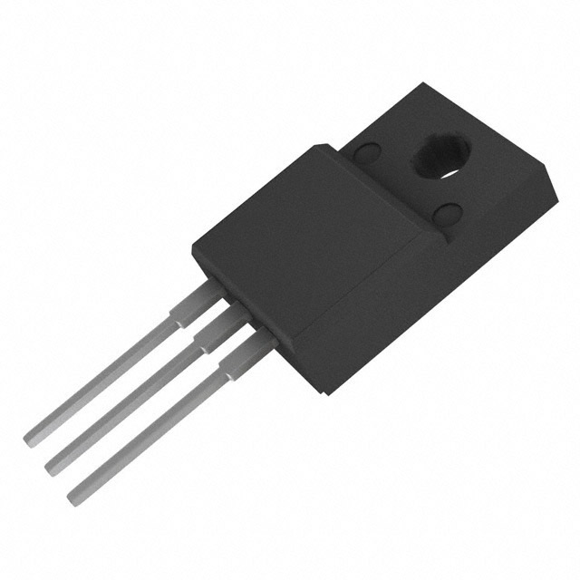
IXTH14N80 N-Channel 800V 14A MOSFET Equivalent & Substitute Parts
Part Overview
The IXTH14N80 is an N-Channel metal oxide semiconductor field-effect transistor (MOSFET) rated for 800V drain-to-source voltage with 14A continuous drain current at 25°C. Manufactured by IXYS in the MegaMOS™ series, this device is packaged in a through-hole TO-247 configuration and rated for 300W maximum power dissipation. The part is classified as obsolete, making identification of functionally equivalent alternatives necessary for ongoing design support, maintenance, and production continuity. Substitute parts must maintain compatibility with the 800V voltage class, support equivalent or higher current ratings, and operate within the same temperature range to ensure direct replacement capability.
Substiute Parts
Key Parameters
| Parameter | Value | Unit |
|---|---|---|
| Drain-to-Source Voltage (Vdss) | 800 | V |
| Continuous Drain Current (Id) @ 25°C | 14 | A (Tc) |
| Power Dissipation (Max) | 300 | W (Tc) |
| Gate-Source Voltage (Vgs Max) | ±20 | V |
| On-State Resistance (Rds On Max) | 700 | mOhm @ 500mA, 10V |
| Gate Charge (Qg Max) | 170 | nC @ 10V |
| Operating Temperature Range | -55 to 150 | °C (TJ) |
| Mounting Type | Through Hole | TO-247 |
| RoHS Status | ROHS3 Compliant | — |
Substitute Part Grouping Explanation
Substitution of the IXTH14N80 is determined by strict adherence to the following electrical and mechanical parameters:
Primary Substitution Criteria:
- Drain-to-Source Voltage (Vdss): Must equal 800V
- Continuous Drain Current (Id): Must equal or exceed 14A at 25°C
- FET Type: N-Channel only
- Technology: Metal Oxide MOSFET
- Operating Temperature Range: Must encompass -55°C to 150°C minimum
- Mounting Type: Through Hole
- RoHS Compliance: ROHS3 Compliant
Secondary Compatibility Factors:
- Gate-Source Voltage (Vgs Max): ±20V minimum
- On-State Resistance (Rds On): Lower values indicate improved performance
- Power Dissipation: Equal or greater than 300W
- Package Type: TO-247 or equivalent through-hole package
Substitute parts are grouped into two categories: Direct Replacements (matching TO-247 package and current rating) and Functional Equivalents (meeting voltage and current specifications with alternative packaging or performance characteristics).
Parameter Comparison
| Parameter | IXTH14N80 | STW13N80K5 | STW12NK80Z | STW10NK80Z | STW11NM80 | FQAF13N80 | STP8N80K5 |
|---|---|---|---|---|---|---|---|
| Manufacturer | IXYS | STMicroelectronics | STMicroelectronics | STMicroelectronics | STMicroelectronics | onsemi | STMicroelectronics |
| Vdss (V) | 800 | 800 | 800 | 800 | 800 | 800 | 800 |
| Id @ 25°C (A) | 14 | 12 | 10.5 | 9 | 11 | 8 | 6 |
| Rds On Max (mOhm) | 700 @ 500mA | 450 @ 6A | 750 @ 5.25A | 900 @ 4.5A | 400 @ 5.5A | 750 @ 4A | 950 @ 3A |
| Power Dissipation Max (W) | 300 | 190 | 190 | 160 | 150 | 120 | 110 |
| Gate Charge Qg Max (nC) | 170 @ 10V | 29 @ 10V | 87 @ 10V | 72 @ 10V | 43.6 @ 10V | 88 @ 10V | 16.5 @ 10V |
| Vgs Max (V) | ±20 | ±30 | ±30 | ±30 | ±30 | ±30 | ±30 |
| Operating Temp Range (°C) | -55 to 150 | -55 to 150 | -55 to 150 | -55 to 150 | -65 to 150 | -55 to 150 | -55 to 150 |
| Package Type | TO-247 | TO-247-3 | TO-247-3 | TO-247-3 | TO-247-3 | TO-3P-3 | TO-220-3 |
| Product Status | Obsolete | Active | Active | Active | Active | Obsolete | Active |
| RoHS Status | ROHS3 Compliant | ROHS3 Compliant | ROHS3 Compliant | ROHS3 Compliant | ROHS3 Compliant | ROHS3 Compliant | ROHS3 Compliant |
Engineering Selection Recommendations
Direct Replacement (Preferred):
STW13N80K5 (STMicroelectronics) is the primary substitute for the IXTH14N80. This device maintains the 800V Vdss rating, operates within the required temperature range (-55°C to 150°C), and is packaged in TO-247-3 through-hole configuration. With 12A continuous drain current, it approaches the original 14A specification. The STW13N80K5 is active in production status, ensuring long-term availability and supply chain stability. RoHS3 compliance and REACH unaffected status align with the original part's regulatory requirements.
Secondary Alternatives (Current Derating Required):
STW12NK80Z and STW10NK80Z provide functional equivalence at reduced current ratings (10.5A and 9A respectively). These parts maintain 800V Vdss, TO-247-3 packaging, and full temperature range compatibility. Selection of these alternatives requires circuit analysis to confirm that reduced current capacity does not compromise system performance. Both parts are active in production and fully compliant with RoHS3 and REACH requirements.
Lower Current Applications:
STW11NM80 (11A) and FQAF13N80 (8A) are suitable for applications where the 14A rating of the original part exceeds system requirements. The STW11NM80 extends the operating temperature range to -65°C, providing enhanced low-temperature performance. FQAF13N80, though obsolete, remains available in inventory and maintains full electrical compatibility within its current rating.
Lowest Current Option:
STP8N80K5 (6A) is applicable only to systems requiring significantly reduced current capacity. This part is packaged in TO-220-3 rather than TO-247, requiring PCB layout modification. Selection of this alternative is limited to applications where thermal and current requirements are substantially lower than the original design specification.
Compliance and Availability:
All recommended substitutes maintain ROHS3 compliance and REACH unaffected status. Active production status for STW13N80K5, STW12NK80Z, STW10NK80Z, and STW11NM80 ensures sustained availability and technical support. Inventory levels vary; STW13N80K5 and STW12NK80Z maintain adequate stock for production requirements.
Frequently Asked Questions (FAQ)
Q: Can the STW13N80K5 directly replace the IXTH14N80 without circuit modification?
A: The STW13N80K5 is electrically compatible with the IXTH14N80 within the specified parameters. Both devices operate at 800V Vdss, support the required temperature range, and are packaged in TO-247 through-hole configuration. The 12A rating of the STW13N80K5 versus the 14A rating of the IXTH14N80 requires verification that circuit current demands do not exceed 12A continuous operation. Pin configuration and gate drive requirements are identical.
Q: What is the impact of selecting a substitute with lower continuous drain current?
A: Substitutes with lower current ratings (STW12NK80Z at 10.5A, STW10NK80Z at 9A) require circuit analysis to confirm that maximum operating current remains below the substitute part's rating. Exceeding the rated current causes excessive junction temperature rise and potential device failure. Thermal management and duty cycle analysis are necessary to validate suitability.
Q: Are TO-247-3 and TO-247 packages mechanically interchangeable?
A: TO-247 and TO-247-3 designations refer to the same physical package with three leads. The "-3" suffix indicates the three-terminal configuration. These packages are mechanically and electrically interchangeable on PCBs designed for TO-247 mounting.
Q: Why is the FQAF13N80 listed as a substitute if it is obsolete?
A: The FQAF13N80 is included because it meets the electrical substitution criteria (800V Vdss, N-Channel MOSFET, through-hole mounting, RoHS3 compliance) and maintains current inventory availability. Obsolete status indicates discontinued production; however, existing stock remains suitable for applications where the 8A current rating is adequate. New designs should prioritize active production alternatives.
Q: What is the significance of gate charge (Qg) differences among substitute parts?
A: Gate charge affects switching speed and gate drive circuit requirements. The IXTH14N80 specifies 170 nC gate charge, while substitutes range from 16.5 nC (STP8N80K5) to 88 nC (STW12NK80Z and FQAF13N80). Lower gate charge enables faster switching and reduced gate drive power consumption. Higher gate charge requires proportionally longer switching times. Gate drive circuit design must accommodate the substitute part's gate charge specification to ensure proper switching performance.
Q: Can the STP8N80K5 be used in applications originally designed for the IXTH14N80?
A: The STP8N80K5 is suitable only for applications where continuous drain current requirements do not exceed 6A. This represents a 57% reduction from the original 14A specification. Additionally, the STP8N80K5 is packaged in TO-220-3 rather than TO-247, requiring PCB layout modification. Use of this substitute is limited to significantly derated applications or new designs with reduced current requirements.
Q: How do I verify that a substitute part is compatible with my circuit?
A: Compatibility verification requires comparison of the following parameters: (1) Drain-to-Source Voltage (Vdss) must equal or exceed circuit maximum voltage; (2) Continuous Drain Current (Id) must equal or exceed maximum circuit current at 25°C; (3) Operating temperature range must encompass circuit ambient and junction temperature extremes; (4) Gate-Source Voltage (Vgs) must accommodate gate drive circuit voltage levels; (5) On-State Resistance (Rds On) must be evaluated for thermal impact; (6) Package type must be compatible with PCB layout. Consult device datasheets for complete electrical specifications.
Q: What is the advantage of STW11NM80 over other substitutes?
A: The STW11NM80 extends the minimum operating temperature to -65°C compared to -55°C for most alternatives. This enhanced low-temperature capability is beneficial for applications requiring operation in extreme cold environments. The 11A continuous drain current provides reasonable current capacity while maintaining 800V Vdss and TO-247-3 packaging. The MDmesh™ technology series offers optimized on-state resistance characteristics.
Alternative Parts

SJ6012L2TP
Littelfuse Inc.
6 Alternative Parts

JMK107BBJ476MA-RE
Taiyo Yuden
10 Alternative Parts

GMK107BBJ475MA-T
Taiyo Yuden
5 Alternative Parts
SJ6020N2ARP
Littelfuse Inc.
3 Alternative Parts
SJ6025R2ATP
Littelfuse Inc.
4 Alternative Parts

2474-05L
API Delevan Inc.
1 Alternative Parts

4590R-684K
API Delevan Inc.
1 Alternative Parts

CM6560R-334
API Delevan Inc.
1 Alternative Parts

CM6460-104
API Delevan Inc.
1 Alternative Parts

5526-12
API Delevan Inc.
1 Alternative Parts