


Request Quote
(Ships tomorrow)
IXTF03N400 Equivalent & Substitute Parts
Part Overview
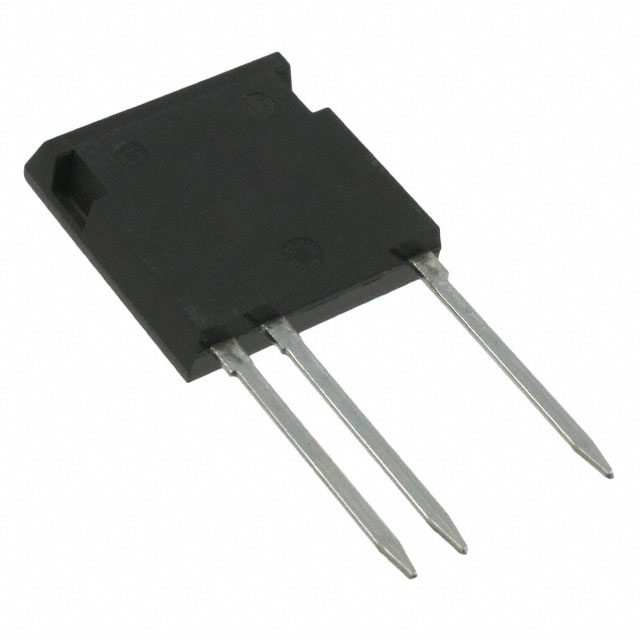
The IXTF03N400 is an N-Channel MOSFET rated for 4000 V drain-to-source voltage with 300 mA continuous drain current and 70 W power dissipation. This device is manufactured by IXYS in the ISOPLUS i4-PAC™ through-hole package. The IXTF03N400 is classified as obsolete, making identification of equivalent substitute parts necessary for ongoing design support and component procurement.
Substiute Parts
Key Parameters
| Parameter | Value | Unit |
|---|---|---|
| Drain to Source Voltage (Vdss) | 4000 | V |
| Continuous Drain Current (Id) @ 25°C | 300 | mA |
| On-State Resistance (Rds On Max) @ Id, Vgs | 300 @ 150mA, 10V | Ohm |
| Gate Threshold Voltage (Vgs(th) Max) @ Id | 4 @ 250µA | V |
| Gate Charge (Qg Max) @ Vgs | 16.3 @ 10V | nC |
| Input Capacitance (Ciss Max) @ Vds | 435 @ 25V | pF |
| Power Dissipation (Max) | 70 | W |
| Operating Temperature Range | -55 to 150 | °C (TJ) |
| Mounting Type | Through Hole | - |
| Package | i4-Pac™-5 (3 Leads) | - |
Substitute Part Grouping Explanation
Substitution of the IXTF03N400 is determined by compatibility across the following critical parameters:
Package and Mounting Compatibility: Both the main part and substitute must use the ISOPLUS i4-PAC™ through-hole package with identical pinout configuration (i4-Pac™-5, 3 Leads).
Voltage Rating: The substitute part must maintain or exceed the 4000 V drain-to-source voltage specification to ensure safe operation in the original application circuit.
Current Handling: The substitute must support the required continuous drain current at 25°C. Derating may apply based on specific application thermal conditions.
Gate Drive Voltage: The substitute must operate with the same gate drive voltage (10 V) to ensure compatibility with existing gate driver circuits.
Temperature Range: The substitute must support the full operating temperature range of -55°C to 150°C (TJ).
Electrical Characteristics: On-state resistance, gate threshold voltage, gate charge, and input capacitance must fall within acceptable ranges for the application to maintain performance and switching behavior.
The IXTF02N450 meets these substitution criteria while offering enhanced voltage rating and active product status.
Parameter Comparison
| Parameter | IXTF03N400 | IXTF02N450 | Unit |
|---|---|---|---|
| Manufacturer | IXYS | IXYS | - |
| FET Type | N-Channel | N-Channel | - |
| Technology | MOSFET (Metal Oxide) | MOSFET (Metal Oxide) | - |
| Drain to Source Voltage (Vdss) | 4000 | 4500 | V |
| Continuous Drain Current (Id) @ 25°C | 300 | 200 | mA |
| Drive Voltage (Max Rds On) | 10 | 10 | V |
| Rds On (Max) @ Id, Vgs | 300 @ 150mA, 10V | 750 @ 10mA, 10V | Ohm |
| Vgs(th) (Max) @ Id | 4 @ 250µA | 6.5 @ 250µA | V |
| Gate Charge (Qg Max) @ Vgs | 16.3 @ 10V | 10.4 @ 10V | nC |
| Vgs (Max) | ±20 | ±20 | V |
| Input Capacitance (Ciss Max) @ Vds | 435 @ 25V | 256 @ 25V | pF |
| Power Dissipation (Max) | 70 | 78 | W |
| Operating Temperature Range | -55 to 150 | -55 to 150 | °C (TJ) |
| Mounting Type | Through Hole | Through Hole | - |
| Package | i4-Pac™-5 (3 Leads) | i4-Pac™-5 (3 Leads) | - |
| Moisture Sensitivity Level (MSL) | 1 (Unlimited) | 1 (Unlimited) | - |
| ECCN | EAR99 | EAR99 | - |
| HTSUS | 8541.29.0095 | 8541.29.0095 | - |
Engineering Selection Recommendations
Product Status Consideration: The IXTF03N400 is classified as obsolete. The IXTF02N450 is an active product with current manufacturing support and availability. Selection of the IXTF02N450 ensures access to ongoing supply and technical documentation.
Compliance and Certifications: Both parts share identical ECCN (EAR99) and HTSUS (8541.29.0095) classifications. The IXTF02N450 carries RoHS3 compliance and REACH unaffected status, providing additional regulatory alignment for modern applications.
Electrical Performance Trade-offs: The IXTF02N450 provides 500 V higher voltage rating (4500 V vs. 4000 V), supporting applications with increased voltage margins. However, continuous drain current is reduced to 200 mA compared to 300 mA in the IXTF03N400. Gate charge is lower (10.4 nC vs. 16.3 nC), reducing switching losses. Input capacitance is reduced (256 pF vs. 435 pF), improving switching speed.
Application Compatibility: The IXTF02N450 is suitable for applications where the 200 mA current rating is sufficient and the higher voltage rating provides design margin. Applications requiring the full 300 mA continuous current of the IXTF03N400 must evaluate whether the IXTF02N450 meets current requirements or if alternative solutions are necessary.
Frequently Asked Questions (FAQ)
Q: Can the IXTF02N450 directly replace the IXTF03N400 in all applications?
A: Direct replacement is possible only when the application current requirement does not exceed 200 mA continuous drain current. The IXTF02N450 provides higher voltage rating (4500 V vs. 4000 V) and lower gate charge, which are generally beneficial. However, applications requiring the full 300 mA rating of the IXTF03N400 must confirm that the IXTF02N450 current specification is adequate for the specific circuit design.
Q: Are the packages identical between these two parts?
A: Yes. Both the IXTF03N400 and IXTF02N450 use the ISOPLUS i4-PAC™ through-hole package with i4-Pac™-5 (3 Leads) configuration. Pinout and mechanical dimensions are identical, allowing direct socket compatibility.
Q: What is the significance of the higher gate threshold voltage in the IXTF02N450?
A: The IXTF02N450 has a gate threshold voltage of 6.5 V compared to 4 V in the IXTF03N400. This higher threshold requires slightly higher gate drive voltage to achieve full on-state conduction. However, both parts operate with 10 V gate drive voltage, which is sufficient for both devices. Gate driver circuits designed for the IXTF03N400 will function with the IXTF02N450.
Q: Why is the on-state resistance specification different between the two parts?
A: The IXTF03N400 specifies Rds On at 150 mA drain current (300 Ohm), while the IXTF02N450 specifies Rds On at 10 mA drain current (750 Ohm). These measurements are taken at different operating points. The IXTF02N450's higher Rds On value reflects its lower current rating and different die design. Direct resistance comparison requires evaluation at equivalent operating conditions.
Q: Is the IXTF02N450 suitable for high-frequency switching applications?
A: The IXTF02N450 exhibits lower gate charge (10.4 nC vs. 16.3 nC) and lower input capacitance (256 pF vs. 435 pF) compared to the IXTF03N400. These characteristics generally support faster switching transitions and reduced switching losses, making the IXTF02N450 favorable for high-frequency applications within its 200 mA current rating.
Q: What regulatory advantages does the IXTF02N450 offer?
A: The IXTF02N450 carries RoHS3 compliance and REACH unaffected status, providing alignment with current environmental and chemical regulations. The IXTF03N400 does not specify these certifications. For applications subject to RoHS or REACH requirements, the IXTF02N450 is the appropriate selection.
Q: Are there inventory considerations for these parts?
A: The IXTF03N400 is obsolete with 966 pieces in stock. The IXTF02N450 is an active product with 1311 pieces in stock. For new designs or long-term production, the IXTF02N450 provides assured supply continuity.
Alternative Parts

SJ6012L2TP
Littelfuse Inc.
6 Alternative Parts

JMK107BBJ476MA-RE
Taiyo Yuden
10 Alternative Parts

GMK107BBJ475MA-T
Taiyo Yuden
5 Alternative Parts
SJ6020N2ARP
Littelfuse Inc.
3 Alternative Parts
SJ6025R2ATP
Littelfuse Inc.
4 Alternative Parts

2474-05L
API Delevan Inc.
1 Alternative Parts

4590R-684K
API Delevan Inc.
1 Alternative Parts

CM6560R-334
API Delevan Inc.
1 Alternative Parts

CM6460-104
API Delevan Inc.
1 Alternative Parts

5526-12
API Delevan Inc.
1 Alternative Parts