


Request Quote
(Ships tomorrow)
IXKC13N80C N-Channel 800V 13A MOSFET Equivalent & Substitute Parts
Part Overview
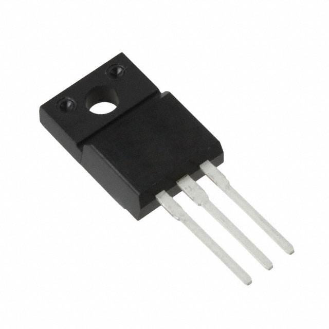
The IXKC13N80C is an N-Channel 800V 13A MOSFET manufactured by IXYS in the CoolMOS™ series, housed in the ISOPLUS220™ through-hole package. This device is classified as obsolete, making identification of functionally equivalent substitute parts essential for ongoing design support and production continuity. The IXKC13N80C serves high-voltage switching applications requiring 800V drain-to-source voltage capability with moderate current handling at 13A continuous drain current.
Substiute Parts
Key Parameters
| Parameter | Value | Unit |
|---|---|---|
| Drain to Source Voltage (Vdss) | 800 | V |
| Current - Continuous Drain (Id) @ 25°C | 13 | A (Tc) |
| Rds On (Max) @ Id, Vgs | 290 mOhm @ 9A, 10V | mOhm |
| Gate Charge (Qg) (Max) @ Vgs | 90 | nC @ 10V |
| Input Capacitance (Ciss) (Max) @ Vds | 2300 | pF @ 25V |
| Vgs(th) (Max) @ Id | 4 | V @ 1mA |
| Vgs (Max) | ±20 | V |
| Operating Temperature Range | -55 to 150 | °C (TJ) |
| Mounting Type | Through Hole | — |
| Package / Case | ISOPLUS220™ | — |
| FET Type | N-Channel | — |
| Technology | MOSFET (Metal Oxide) | — |
Substitute Part Grouping Explanation
Substitution of the IXKC13N80C is determined by strict alignment of the following critical electrical and mechanical parameters:
Electrical Compatibility Criteria:
- Drain to Source Voltage (Vdss): Must equal or exceed 800V
- FET Type: Must be N-Channel
- Technology: Must be MOSFET (Metal Oxide)
- Gate Charge (Qg): Lower values reduce switching losses; values within 40–177 nC are acceptable for equivalent switching performance
- Rds On (Max): Values at or below 295 mOhm maintain thermal performance equivalence
- Vgs(th) and Vgs (Max): Must support standard gate drive circuits (±20V to ±30V range)
- Input Capacitance (Ciss): Values between 1600–2320 pF maintain gate drive compatibility
Mechanical Compatibility Criteria:
- Mounting Type: Must be Through Hole
- Package / Case: Substitutes in TO-220-3 Full Pack are mechanically compatible with ISOPLUS220™ in through-hole applications
Current Handling: Substitute parts with continuous drain current (Id) of 17A or higher provide current margin above the 13A requirement of the main part.
All three substitute parts meet these criteria and are classified as Active products with current manufacturing status.
Parameter Comparison
| Parameter | IXKC13N80C | SPA17N80C3XKSA1 | STF18NM80 | STF25N80K5 |
|---|---|---|---|---|
| Manufacturer | IXYS | Infineon Technologies | STMicroelectronics | STMicroelectronics |
| Drain to Source Voltage (Vdss) | 800 V | 800 V | 800 V | 800 V |
| Current - Continuous Drain (Id) @ 25°C | 13 A (Tc) | 17 A (Tc) | 17 A (Tc) | 19.5 A (Tc) |
| Rds On (Max) @ Id, Vgs | 290 mOhm @ 9A, 10V | 290 mOhm @ 11A, 10V | 295 mOhm @ 8.5A, 10V | 260 mOhm @ 19.5A, 10V |
| Gate Charge (Qg) (Max) @ Vgs | 90 nC @ 10V | 177 nC @ 10V | 70 nC @ 10V | 40 nC @ 10V |
| Vgs(th) (Max) @ Id | 4 V @ 1mA | 3.9 V @ 1mA | 5 V @ 250µA | 5 V @ 100µA |
| Vgs (Max) | ±20 V | ±20 V | ±30 V | ±30 V |
| Input Capacitance (Ciss) (Max) @ Vds | 2300 pF @ 25V | 2320 pF @ 25V | 2070 pF @ 50V | 1600 pF @ 100V |
| Operating Temperature Range | -55 to 150 °C (TJ) | -55 to 150 °C (TJ) | 150 °C (TJ) | -55 to 150 °C (TJ) |
| Mounting Type | Through Hole | Through Hole | Through Hole | Through Hole |
| Package / Case | ISOPLUS220™ | TO-220-3 Full Pack | TO-220-3 Full Pack | TO-220-3 Full Pack |
| FET Type | N-Channel | N-Channel | N-Channel | N-Channel |
| Technology | MOSFET (Metal Oxide) | MOSFET (Metal Oxide) | MOSFET (Metal Oxide) | MOSFET (Metal Oxide) |
| Product Status | Obsolete | Active | Active | Active |
| RoHS Status | — | ROHS3 Compliant | ROHS3 Compliant | ROHS3 Compliant |
| REACH Status | REACH Unaffected | REACH Unaffected | REACH Unaffected | REACH Unaffected |
Engineering Selection Recommendations
Product Status Consideration: The IXKC13N80C is classified as obsolete. All three substitute parts—SPA17N80C3XKSA1, STF18NM80, and STF25N80K5—are classified as Active, ensuring long-term availability and manufacturing support.
Compliance and Certification: All substitute parts carry ROHS3 compliance and REACH Unaffected status, meeting current regulatory requirements for electronic component procurement. The main part does not specify RoHS status, making the substitutes preferable for new designs and production environments subject to environmental compliance mandates.
Electrical Performance: All substitutes maintain the 800V Vdss rating and support the required gate drive voltage range. The substitutes provide equal or superior continuous drain current capability (17A–19.5A versus 13A), offering thermal margin in applications operating at or near the original part's current rating.
Thermal and Switching Characteristics: SPA17N80C3XKSA1 and STF25N80K5 maintain the full -55°C to 150°C operating temperature range of the original part. STF18NM80 specifies only the upper temperature limit (150°C), which may be a constraint in applications requiring low-temperature operation below 0°C.
Gate Charge Consideration: STF25N80K5 exhibits the lowest gate charge (40 nC), resulting in reduced switching losses and faster switching transitions. STF18NM80 provides moderate gate charge (70 nC). SPA17N80C3XKSA1 has higher gate charge (177 nC), which may increase switching losses but does not preclude substitution in applications with adequate gate drive capability.
Package Transition: Substitutes use TO-220-3 Full Pack instead of ISOPLUS220™. Both are through-hole packages with compatible pin configurations for standard PCB layouts. Mechanical fit and thermal interface design must be verified for the specific application.
Frequently Asked Questions (FAQ)
Q: Can the SPA17N80C3XKSA1 directly replace the IXKC13N80C?
A: Yes. Both devices share identical Vdss (800V), Rds On (290 mOhm), and Vgs (Max) (±20V) specifications. The SPA17N80C3XKSA1 provides higher continuous drain current (17A versus 13A) and maintains the full -55°C to 150°C operating temperature range. The primary difference is package format: TO-220-3 Full Pack versus ISOPLUS220™. PCB layout modifications may be required to accommodate the different package footprint.
Q: What is the difference between the three substitute parts?
A: All three maintain 800V Vdss and support the original application voltage. Key differences are:
- SPA17N80C3XKSA1: 17A current, 290 mOhm Rds On, 177 nC gate charge, ±20V Vgs (Max)
- STF18NM80: 17A current, 295 mOhm Rds On, 70 nC gate charge, ±30V Vgs (Max), limited to 150°C upper temperature
- STF25N80K5: 19.5A current, 260 mOhm Rds On, 40 nC gate charge, ±30V Vgs (Max), full -55°C to 150°C range
STF25N80K5 offers the lowest on-resistance and gate charge, optimizing for switching efficiency. STF18NM80 provides moderate performance with lower gate charge. SPA17N80C3XKSA1 maintains closest electrical alignment to the original part.
Q: Are there package compatibility concerns?
A: The IXKC13N80C uses ISOPLUS220™ packaging, while all substitutes use TO-220-3 Full Pack. Both are through-hole packages with three leads. Pin assignments are compatible for standard N-Channel MOSFET applications (Gate, Drain, Source). Physical dimensions and thermal interface characteristics differ; PCB layout and heatsink mounting must be re-evaluated for the new package geometry.
Q: Which substitute is best for low-temperature applications?
A: SPA17N80C3XKSA1 and STF25N80K5 both specify the full -55°C to 150°C operating temperature range, matching the original part. STF18NM80 specifies only 150°C (upper limit), making it unsuitable for applications requiring operation below 0°C.
Q: Do all substitutes meet current regulatory requirements?
A: Yes. All three substitute parts are ROHS3 compliant and REACH Unaffected. The original IXKC13N80C does not specify RoHS status. For new designs and production environments subject to environmental compliance mandates, the substitutes are preferable.
Q: What is the impact of different gate charge values?
A: Gate charge (Qg) affects switching speed and gate drive power dissipation. STF25N80K5 (40 nC) switches fastest with lowest gate drive losses. STF18NM80 (70 nC) provides moderate switching speed. SPA17N80C3XKSA1 (177 nC) requires higher gate drive current but does not preclude substitution in applications with adequate gate drive capability. Selection depends on switching frequency and gate drive circuit design.
Q: Can I use these substitutes in existing PCB designs without modification?
A: No. The package change from ISOPLUS220™ to TO-220-3 Full Pack requires PCB footprint modification. Pin assignments are compatible, but physical layout, mounting hole positions, and thermal interface design must be re-evaluated. Heatsink mounting and thermal management may require redesign.
Alternative Parts

SJ6012L2TP
Littelfuse Inc.
6 Alternative Parts

JMK107BBJ476MA-RE
Taiyo Yuden
10 Alternative Parts

GMK107BBJ475MA-T
Taiyo Yuden
5 Alternative Parts
SJ6020N2ARP
Littelfuse Inc.
3 Alternative Parts
SJ6025R2ATP
Littelfuse Inc.
4 Alternative Parts

2474-05L
API Delevan Inc.
1 Alternative Parts

4590R-684K
API Delevan Inc.
1 Alternative Parts

CM6560R-334
API Delevan Inc.
1 Alternative Parts

CM6460-104
API Delevan Inc.
1 Alternative Parts

5526-12
API Delevan Inc.
1 Alternative Parts