


Request Quote
(Ships tomorrow)
IXGT60N60C2 Equivalent & Substitute Parts
Part Overview
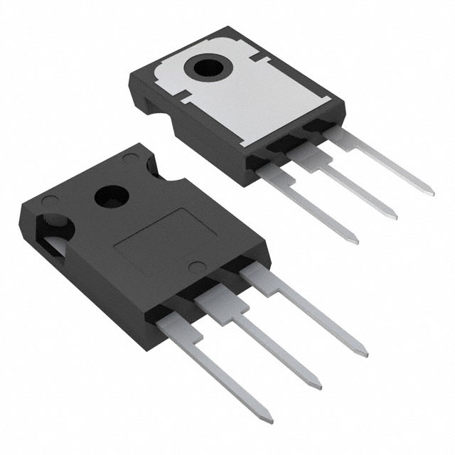
The IXGT60N60C2 is an IGBT (Insulated Gate Bipolar Transistor) rated for 600V collector-emitter breakdown voltage with a maximum collector current of 75A and 480W power dissipation. Manufactured by IXYS in the HiPerFAST™ series, this component features a PT (Punch-Through) IGBT type in a Surface Mount TO-268AA package configuration.
The IXGT60N60C2 is classified as obsolete. Identifying equivalent and substitute parts is necessary to maintain design continuity, ensure supply chain availability, and support ongoing production requirements for applications utilizing this component.
Substiute Parts
Key Parameters
| Parameter | Value | Unit |
|---|---|---|
| Voltage - Collector Emitter Breakdown (Max) | 600 | V |
| Current - Collector (Ic) (Max) | 75 | A |
| Current - Collector Pulsed (Icm) | 300 | A |
| Power - Max | 480 | W |
| Vce(on) (Max) @ Vge, Ic | 2.5V @ 15V, 50A | V |
| Gate Charge | 146 | nC |
| Switching Energy (off) | 480 | µJ |
| Td (on/off) @ 25°C | 18ns/95ns | ns |
| Operating Temperature Range | -55 to 150 | °C (TJ) |
| Mounting Type | Surface Mount | - |
| Package / Case | TO-268-3, D³Pak (2 Leads + Tab) | - |
Substitute Part Grouping Explanation
Substitution of the IXGT60N60C2 is evaluated based on the following critical electrical and mechanical parameters:
Voltage Rating: The substitute must support the application voltage requirement. The IXGT60N60C2 operates at 600V maximum collector-emitter breakdown voltage. Substitute parts with equal or higher voltage ratings are acceptable.
Current Rating: The substitute must accommodate the maximum collector current demand. The IXGT60N60C2 is rated for 75A continuous collector current. Substitute parts with equal or higher current ratings are acceptable.
Power Dissipation: The substitute must handle the thermal load. The IXGT60N60C2 is rated for 480W maximum power dissipation. Substitute parts with equal or higher power ratings are acceptable.
On-State Voltage (Vce(on)): This parameter affects conduction losses and thermal performance. The IXGT60N60C2 specifies 2.5V maximum at 15V gate voltage and 50A collector current.
Switching Characteristics: Gate charge, switching delay times (Td on/off), and switching energy influence circuit performance and EMI behavior. The IXGT60N60C2 exhibits 146nC gate charge and 18ns/95ns on/off delay times.
Package and Mounting: The IXGT60N60C2 uses Surface Mount TO-268AA packaging. Substitute parts may use different package types if thermal and electrical performance requirements are met and PCB layout can accommodate the alternative form factor.
Operating Temperature Range: The IXGT60N60C2 operates from -55°C to 150°C junction temperature. Substitute parts with equal or wider temperature ranges are acceptable.
Parameter Comparison
| Parameter | IXGT60N60C2 | STGW60H65FB | Unit |
|---|---|---|---|
| Manufacturer | IXYS | STMicroelectronics | - |
| IGBT Type | PT (Punch-Through) | Trench Field Stop | - |
| Voltage - Collector Emitter Breakdown (Max) | 600 | 650 | V |
| Current - Collector (Ic) (Max) | 75 | 80 | A |
| Current - Collector Pulsed (Icm) | 300 | 240 | A |
| Power - Max | 480 | 375 | W |
| Vce(on) (Max) @ Vge, Ic | 2.5V @ 15V, 50A | 2.3V @ 15V, 60A | V |
| Gate Charge | 146 | 306 | nC |
| Switching Energy (off) | 480 | 626 | µJ |
| Td (on/off) @ 25°C | 18ns/95ns | 51ns/160ns | ns |
| Operating Temperature Range | -55 to 150 | -55 to 175 | °C (TJ) |
| Mounting Type | Surface Mount | Through Hole | - |
| Package / Case | TO-268-3 (D³Pak) | TO-247-3 | - |
| Product Status | Obsolete | Active | - |
Engineering Selection Recommendations
STGW60H65FB as Substitute for IXGT60N60C2
The STGW60H65FB from STMicroelectronics is an active product suitable for substitution in applications previously designed with the IXGT60N60C2. The following factors support this substitution:
Electrical Compatibility: The STGW60H65FB exceeds the voltage rating (650V vs. 600V) and current rating (80A vs. 75A) of the original part, providing margin for application requirements. The on-state voltage is lower (2.3V vs. 2.5V), resulting in reduced conduction losses.
Product Status: The STGW60H65FB is classified as Active, ensuring ongoing availability and manufacturer support. The IXGT60N60C2 is obsolete, making the STGW60H65FB a necessary alternative for continued supply.
Compliance and Certifications: Both parts carry identical REACH Status (REACH Unaffected) and ECCN classification (EAR99). The STGW60H65FB is RoHS3 Compliant, meeting current regulatory requirements.
Temperature Performance: The STGW60H65FB supports an extended operating temperature range (-55°C to 175°C) compared to the IXGT60N60C2 (-55°C to 150°C), providing additional thermal margin.
Package Consideration: The STGW60H65FB uses Through Hole TO-247 packaging, whereas the IXGT60N60C2 uses Surface Mount TO-268AA packaging. PCB layout modification is required for this substitution. The TO-247 package provides improved thermal performance through direct mounting to heatsinks.
Switching Characteristics: The STGW60H65FB exhibits higher gate charge (306nC vs. 146nC) and longer switching delay times (51ns/160ns vs. 18ns/95ns). Circuit design verification is necessary to confirm compatibility with gate drive circuitry and switching frequency requirements.
Power Dissipation: The STGW60H65FB is rated for 375W maximum power dissipation, which is lower than the IXGT60N60C2 (480W). Application thermal analysis is required to confirm adequate thermal management with the substitute part.
Frequently Asked Questions (FAQ)
Q: Can the STGW60H65FB directly replace the IXGT60N60C2 without circuit modifications?
A: The STGW60H65FB is electrically compatible for voltage and current requirements. However, the different package type (Through Hole TO-247 vs. Surface Mount TO-268AA) requires PCB layout changes. Additionally, the higher gate charge (306nC vs. 146nC) and longer switching times may require gate drive circuit evaluation to ensure proper operation at the intended switching frequency.
Q: What are the key differences in switching performance between these parts?
A: The IXGT60N60C2 exhibits faster switching characteristics with 18ns turn-on delay and 95ns turn-off delay, compared to the STGW60H65FB at 51ns and 160ns respectively. The IXGT60N60C2 also has lower gate charge (146nC vs. 306nC) and lower switching energy (480µJ off vs. 626µJ off). These differences affect EMI performance and gate drive power requirements.
Q: Is the STGW60H65FB suitable for high-frequency switching applications?
A: The STGW60H65FB has slower switching characteristics than the IXGT60N60C2. Applications operating at high switching frequencies should verify that the gate drive circuitry can accommodate the higher gate charge and that the increased switching losses remain within thermal limits.
Q: What thermal considerations apply when substituting the STGW60H65FB?
A: The STGW60H65FB is rated for 375W maximum power dissipation, compared to 480W for the IXGT60N60C2. The TO-247 package provides superior thermal coupling to external heatsinks compared to the Surface Mount TO-268AA package. Thermal analysis is required to confirm that application power dissipation remains within the 375W limit with the substitute part.
Q: Are there compliance or regulatory differences between these parts?
A: Both parts share identical REACH Status (REACH Unaffected) and ECCN classification (EAR99). The STGW60H65FB is RoHS3 Compliant, whereas the IXGT60N60C2 compliance status is not specified in the provided data. The STGW60H65FB meets current regulatory requirements for new designs.
Q: What is the difference between PT (Punch-Through) and Trench Field Stop IGBT types?
A: The IXGT60N60C2 uses PT (Punch-Through) technology, while the STGW60H65FB uses Trench Field Stop technology. These represent different semiconductor manufacturing approaches. The Trench Field Stop design in the STGW60H65FB typically offers improved switching performance and lower switching losses in modern applications, though the specific performance trade-offs depend on application operating conditions.
Q: Can the STGW60H65FB handle the same pulsed current as the IXGT60N60C2?
A: The IXGT60N60C2 is rated for 300A pulsed collector current, while the STGW60H65FB is rated for 240A. Applications requiring the full 300A pulsed current capability should verify that the STGW60H65FB meets the specific pulse duration and duty cycle requirements.
Alternative Parts

SJ6012L2TP
Littelfuse Inc.
6 Alternative Parts

JMK107BBJ476MA-RE
Taiyo Yuden
10 Alternative Parts

GMK107BBJ475MA-T
Taiyo Yuden
5 Alternative Parts
SJ6020N2ARP
Littelfuse Inc.
3 Alternative Parts
SJ6025R2ATP
Littelfuse Inc.
4 Alternative Parts

2474-05L
API Delevan Inc.
1 Alternative Parts

4590R-684K
API Delevan Inc.
1 Alternative Parts

CM6560R-334
API Delevan Inc.
1 Alternative Parts

CM6460-104
API Delevan Inc.
1 Alternative Parts

5526-12
API Delevan Inc.
1 Alternative Parts