


Request Quote
(Ships tomorrow)
IXGT60N60 IGBT Equivalent & Substitute Parts
Part Overview
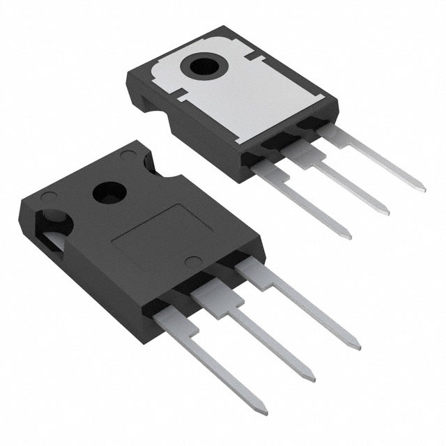
The IXGT60N60 is a 600V, 75A IGBT manufactured by IXYS in a Surface Mount TO-268AA package. This component is classified as obsolete, necessitating identification of equivalent substitute parts for ongoing design requirements and procurement needs. The IGBT PT (Punch-Through) technology operates at maximum junction temperatures from -55°C to 150°C and delivers 300W maximum power dissipation.
Substiute Parts
Key Parameters
| Parameter | Value | Unit |
|---|---|---|
| Voltage - Collector Emitter Breakdown (Max) | 600 | V |
| Current - Collector (Ic) (Max) | 75 | A |
| Current - Collector Pulsed (Icm) | 200 | A |
| Vce(on) (Max) @ Vge, Ic | 1.7V @ 15V, 60A | V |
| Power - Max | 300 | W |
| Gate Charge | 130 | nC |
| Switching Energy (off) | 8 | mJ |
| Td (on/off) @ 25°C | 50/300 | ns |
| Operating Temperature Range | -55 to 150 | °C (TJ) |
| Mounting Type | Surface Mount | - |
| Package / Case | TO-268-3, D³Pak (2 Leads + Tab) | - |
Substitute Part Grouping Explanation
Substitution of the IXGT60N60 is determined by electrical and mechanical compatibility within the following critical parameters:
Voltage Rating: The substitute must support the application voltage with adequate margin. The IXGT60N60 operates at 600V maximum collector-emitter breakdown voltage.
Current Rating: The substitute must accommodate the maximum collector current (Ic) and pulsed collector current (Icm) requirements of the application circuit.
On-State Voltage (Vce(on)): Forward voltage drop at specified gate and collector conditions affects power dissipation and thermal management.
Power Dissipation: Maximum power rating must meet or exceed application requirements.
Gate Charge and Switching Times: These parameters influence gate drive circuit design and switching losses.
Operating Temperature Range: The substitute must support the thermal environment of the application.
Package and Mounting Type: Physical compatibility with PCB layout and thermal management infrastructure.
The STGW60H65FB qualifies as a substitute based on electrical parameter compatibility and superior active product status, despite differences in package type and IGBT technology variant.
Parameter Comparison
| Parameter | IXGT60N60 | STGW60H65FB | Unit |
|---|---|---|---|
| Manufacturer | IXYS | STMicroelectronics | - |
| Product Status | Obsolete | Active | - |
| Voltage - Collector Emitter Breakdown (Max) | 600 | 650 | V |
| Current - Collector (Ic) (Max) | 75 | 80 | A |
| Current - Collector Pulsed (Icm) | 200 | 240 | A |
| Vce(on) (Max) @ Vge, Ic | 1.7V @ 15V, 60A | 2.3V @ 15V, 60A | V |
| Power - Max | 300 | 375 | W |
| Gate Charge | 130 | 306 | nC |
| Switching Energy (off) | 8 | 0.626 | mJ / mJ |
| Td (on/off) @ 25°C | 50/300 | 51/160 | ns |
| Operating Temperature Range | -55 to 150 | -55 to 175 | °C (TJ) |
| Mounting Type | Surface Mount | Through Hole | - |
| Package / Case | TO-268-3, D³Pak | TO-247-3 | - |
| IGBT Type | PT (Punch-Through) | Trench Field Stop | - |
| RoHS Status | Not specified | ROHS3 Compliant | - |
Engineering Selection Recommendations
Product Status Consideration: The IXGT60N60 is classified as obsolete. The STGW60H65FB is an active product from STMicroelectronics, ensuring ongoing availability and manufacturing support.
Compliance and Certifications: The STGW60H65FB carries ROHS3 compliance certification, whereas the IXGT60N60 does not specify RoHS status. Both components are REACH Unaffected and classified under ECCN EAR99.
Electrical Compatibility: The STGW60H65FB provides higher voltage (650V vs. 600V), current (80A vs. 75A), and power (375W vs. 300W) ratings, establishing margin for application requirements. The higher Vce(on) value (2.3V vs. 1.7V) results in increased conduction losses that must be evaluated against thermal management capabilities.
Switching Characteristics: The STGW60H65FB exhibits significantly lower off-state switching energy (626µJ vs. 8mJ) and faster turn-off time (160ns vs. 300ns), reducing switching losses. Higher gate charge (306nC vs. 130nC) requires gate drive circuit evaluation.
Thermal Range: The STGW60H65FB supports extended maximum junction temperature (175°C vs. 150°C), providing additional thermal margin.
Package Transition: Substitution requires transition from Surface Mount TO-268AA to Through Hole TO-247-3 package, necessitating PCB layout and thermal management redesign.
Frequently Asked Questions (FAQ)
Q: Can the STGW60H65FB directly replace the IXGT60N60 without circuit modifications?
A: Direct pin-for-pin replacement is not possible due to package differences (TO-268AA Surface Mount vs. TO-247-3 Through Hole). PCB layout and mounting infrastructure require redesign. Gate drive circuits must be evaluated for compatibility with the higher gate charge specification (306nC vs. 130nC).
Q: What are the implications of the higher Vce(on) value in the STGW60H65FB?
A: The STGW60H65FB exhibits 0.6V higher on-state voltage drop at equivalent test conditions (2.3V vs. 1.7V @ 15V, 60A). This increases conduction losses and heat dissipation. Thermal management design must accommodate the higher power dissipation, though the substitute's 375W maximum rating provides additional margin over the original 300W specification.
Q: How do switching characteristics differ between these components?
A: The STGW60H65FB demonstrates substantially faster turn-off switching (160ns vs. 300ns) and lower off-state switching energy (626µJ vs. 8mJ), reducing switching losses. Turn-on time is comparable (51ns vs. 50ns). These differences affect EMI performance and gate drive timing requirements.
Q: Is the higher gate charge of the STGW60H65FB a concern?
A: The STGW60H65FB requires 306nC gate charge compared to 130nC for the IXGT60N60. Gate drive circuits must supply sufficient charge within acceptable time frames. This may require gate driver evaluation or redesign to ensure proper switching performance and prevent gate voltage overshoot.
Q: What voltage margin does the STGW60H65FB provide?
A: The STGW60H65FB is rated for 650V collector-emitter breakdown voltage compared to 600V for the IXGT60N60, providing 50V additional margin. This supports applications operating near the original 600V specification with improved reliability margin.
Q: Are there compliance differences between these components?
A: The STGW60H65FB carries ROHS3 compliance certification. The IXGT60N60 does not specify RoHS status. Both components are REACH Unaffected. Applications requiring RoHS compliance must use the STGW60H65FB.
Q: What is the impact of the extended operating temperature range?
A: The STGW60H65FB supports junction temperatures to 175°C compared to 150°C for the IXGT60N60. This provides 25°C additional thermal margin, beneficial for high-temperature applications or designs with limited thermal management capacity.
Alternative Parts

SJ6012L2TP
Littelfuse Inc.
6 Alternative Parts

JMK107BBJ476MA-RE
Taiyo Yuden
10 Alternative Parts

GMK107BBJ475MA-T
Taiyo Yuden
5 Alternative Parts
SJ6020N2ARP
Littelfuse Inc.
3 Alternative Parts
SJ6025R2ATP
Littelfuse Inc.
4 Alternative Parts

2474-05L
API Delevan Inc.
1 Alternative Parts

4590R-684K
API Delevan Inc.
1 Alternative Parts

CM6560R-334
API Delevan Inc.
1 Alternative Parts

CM6460-104
API Delevan Inc.
1 Alternative Parts

5526-12
API Delevan Inc.
1 Alternative Parts