


Request Quote
(Ships tomorrow)
IXGR40N60C IGBT Equivalent & Substitute Parts
Part Overview
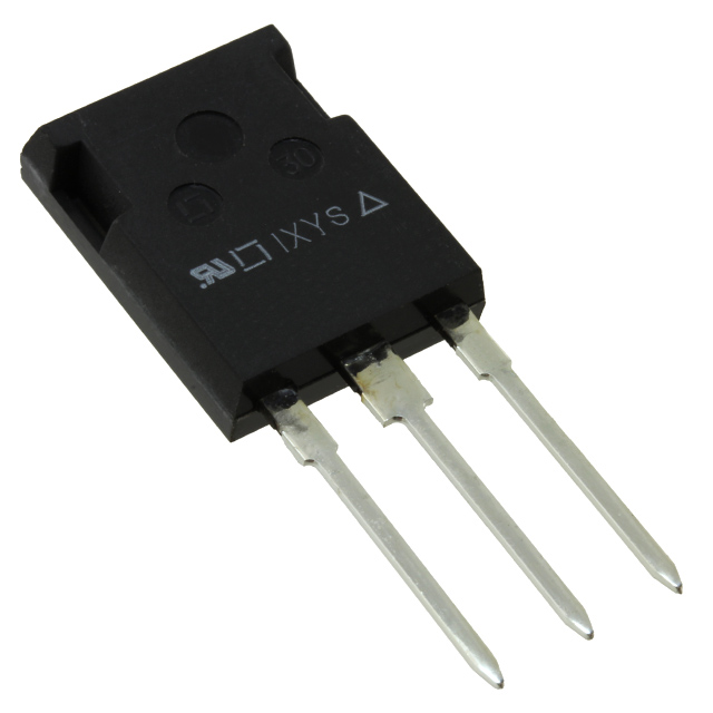
The IXGR40N60C is a 600V, 75A IGBT manufactured by IXYS in the HiPerFAST™ series, housed in a TO-247-3 package (ISOPLUS247™). This component is rated for 200W maximum power dissipation and features a switching energy specification of 850µJ (off) with gate charge of 116 nC. The part is currently classified as obsolete, necessitating identification of functionally equivalent alternatives for ongoing system support and new designs.
Substiute Parts
Key Parameters
| Parameter | IXGR40N60C |
|---|---|
| Voltage - Collector Emitter Breakdown (Max) | 600 V |
| Current - Collector (Ic) (Max) | 75 A |
| Current - Collector Pulsed (Icm) | 150 A |
| Vce(on) (Max) @ Vge, Ic | 2.7V @ 15V, 40A |
| Power - Max | 200 W |
| Switching Energy (off) | 850µJ |
| Gate Charge | 116 nC |
| Td (on/off) @ 25°C | 25ns/100ns |
| Operating Temperature Range | -55°C ~ 150°C (TJ) |
| Package / Case | TO-247-3 |
| Mounting Type | Through Hole |
| Product Status | Obsolete |
Substitute Part Grouping Explanation
Substitution of the IXGR40N60C is determined by the following critical parameters:
Voltage Rating: All substitute parts must maintain a minimum collector-emitter breakdown voltage of 600V to ensure safe operation within the original design envelope.
Current Rating: The maximum collector current (Ic) must be equal to or greater than 75A. Substitute parts with higher current ratings (80A) provide additional design margin.
Package Compatibility: All substitute parts must use the TO-247-3 through-hole package to ensure mechanical and thermal compatibility with existing PCB layouts and heatsink mounting arrangements.
Input Type: All substitute parts maintain Standard input type, ensuring gate drive circuit compatibility.
Operating Temperature Range: Substitute parts must support the minimum operating range of -55°C to 150°C; extended ranges provide additional design flexibility.
Electrical Characteristics: Vce(on), gate charge, and switching energy parameters are evaluated for functional equivalence within typical application tolerances.
Parameter Comparison
| Parameter | IXGR40N60C | FGH40N60SMD-F085 | NGTB40N60L2WG | STGFW40H65FB |
|---|---|---|---|---|
| Manufacturer | IXYS | onsemi | onsemi | STMicroelectronics |
| Voltage - Collector Emitter Breakdown (Max) | 600 V | 600 V | 600 V | 650 V |
| Current - Collector (Ic) (Max) | 75 A | 80 A | 80 A | 80 A |
| Current - Collector Pulsed (Icm) | 150 A | 120 A | 160 A | 160 A |
| Vce(on) (Max) @ Vge, Ic | 2.7V @ 15V, 40A | 2.5V @ 15V, 40A | 2.61V @ 15V, 40A | 2V @ 15V, 40A |
| Power - Max | 200 W | 349 W | 417 W | 62.5 W |
| Gate Charge | 116 nC | 180 nC | 228 nC | 210 nC |
| Td (on/off) @ 25°C | 25ns/100ns | 18ns/110ns | 98ns/213ns | 40ns/142ns |
| Operating Temperature Range | -55°C ~ 150°C | -55°C ~ 175°C | -55°C ~ 175°C | -55°C ~ 175°C |
| Package / Case | TO-247-3 | TO-247-3 | TO-247-3 | TO-3P-3 Full Pack |
| Product Status | Obsolete | Active | Obsolete | Active |
| IGBT Type | Standard | Field Stop | Trench Field Stop | Trench Field Stop |
Engineering Selection Recommendations
FGH40N60SMD-F085 (onsemi): This part is actively manufactured and meets all critical substitution parameters. It provides 80A collector current (exceeding the 75A requirement), maintains 600V voltage rating, and uses the TO-247-3 package. The Field Stop IGBT type delivers improved switching performance with lower on-time delay (18ns vs. 25ns). The part carries AEC-Q101 automotive qualification and ROHS3 compliance. Extended operating temperature range to 175°C provides additional thermal margin. This is the preferred substitute for applications requiring active product support and automotive-grade reliability.
NGTB40N60L2WG (onsemi): This part meets voltage, current, and package requirements with 80A collector current and 600V rating in TO-247-3 package. However, it is classified as obsolete, limiting its suitability for new designs requiring long-term component availability. The Trench Field Stop architecture provides higher pulsed current capability (160A) and extended temperature range to 175°C. Gate charge and switching delays are significantly higher than the original part, requiring gate drive circuit evaluation.
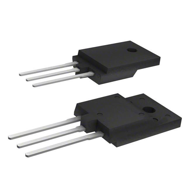
STGFW40H65FB (STMicroelectronics): This part is actively manufactured with ROHS3 compliance and extended operating temperature to 175°C. It provides 80A collector current and uses a TO-3P-3 package (ISOWATT218), which differs from the original TO-247-3 package. This package difference requires PCB layout and heatsink mounting redesign. The 650V voltage rating exceeds requirements. Maximum power rating of 62.5W is significantly lower than the original 200W specification, limiting applicability to lower-power designs. Vce(on) is improved at 2V, but the package incompatibility makes this a conditional substitute requiring mechanical redesign.
Frequently Asked Questions (FAQ)
Q: Can the FGH40N60SMD-F085 directly replace the IXGR40N60C without PCB modifications?
A: Yes. Both parts use the TO-247-3 package with identical pin configuration and through-hole mounting. No PCB layout changes are required. Heatsink mounting interfaces are compatible.
Q: What is the significance of the higher gate charge in substitute parts?
A: The FGH40N60SMD-F085 has 180 nC gate charge versus 116 nC in the original part. This requires gate drive circuits to supply additional charge during switching transitions. Existing gate drive circuits must be evaluated for current capability at the specified switching frequency. Higher gate charge increases switching losses and may require gate resistor adjustment.
Q: Why does the STGFW40H65FB use a different package?
A: The STGFW40H65FB uses TO-3P-3 (ISOWATT218) package instead of TO-247-3. This package has different pin spacing and mounting hole locations, requiring PCB redesign and new heatsink mounting hardware. This package difference makes it unsuitable for direct substitution without mechanical redesign.
Q: Are all substitute parts RoHS compliant?
A: FGH40N60SMD-F085 and STGFW40H65FB are ROHS3 compliant. NGTB40N60L2WG is also ROHS3 compliant. All parts are REACH unaffected and carry EAR99 ECCN classification.
Q: What is the impact of different IGBT types (Standard vs. Field Stop vs. Trench Field Stop)?
A: IGBT type affects switching speed and conduction losses. Field Stop and Trench Field Stop architectures provide faster switching (lower Td on/off) and improved efficiency compared to Standard types. The FGH40N60SMD-F085 Field Stop type offers faster on-switching (18ns vs. 25ns) than the original Standard type, reducing switching losses in high-frequency applications.
Q: Can the NGTB40N60L2WG be used in new production designs?
A: The NGTB40N60L2WG is classified as obsolete. While it meets electrical specifications, its obsolete status limits long-term availability and supply chain reliability. New designs should use the actively manufactured FGH40N60SMD-F085 to ensure component availability throughout the product lifecycle.
Q: What is the operating temperature advantage of substitute parts?
A: The original IXGR40N60C operates to 150°C junction temperature. All substitute parts extend this to 175°C, providing 25°C additional thermal margin. This allows higher ambient operating temperatures or reduced heatsink requirements in thermally constrained applications.
Q: How do switching energy specifications affect circuit design?
A: Switching energy (on and off) determines power dissipation during transitions. The FGH40N60SMD-F085 has 920µJ on-switching versus 850µJ off-switching in the original part. Higher switching energy increases thermal load on the heatsink. Gate drive circuit design must account for these energy levels to ensure proper switching performance and thermal management.
Alternative Parts

SJ6012L2TP
Littelfuse Inc.
6 Alternative Parts

JMK107BBJ476MA-RE
Taiyo Yuden
10 Alternative Parts

GMK107BBJ475MA-T
Taiyo Yuden
5 Alternative Parts
SJ6020N2ARP
Littelfuse Inc.
3 Alternative Parts
SJ6025R2ATP
Littelfuse Inc.
4 Alternative Parts

2474-05L
API Delevan Inc.
1 Alternative Parts

4590R-684K
API Delevan Inc.
1 Alternative Parts

CM6560R-334
API Delevan Inc.
1 Alternative Parts

CM6460-104
API Delevan Inc.
1 Alternative Parts

5526-12
API Delevan Inc.
1 Alternative Parts