


Request Quote
(Ships tomorrow)
IXGR24N60CD1 IGBT Equivalent & Substitute Parts
Part Overview
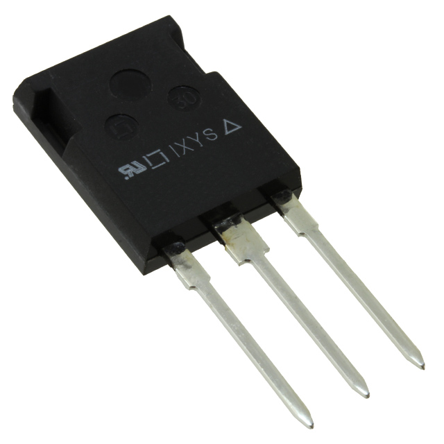
The IXGR24N60CD1 is a 600V, 42A IGBT manufactured by IXYS in the HiPerFAST™ series, housed in an ISOPLUS247™ package for through-hole mounting. This component is classified as obsolete, necessitating identification of functionally equivalent alternatives for ongoing system support and new designs. Substitute parts must maintain electrical compatibility across voltage, current, and thermal operating ranges while accommodating available packaging options.
Substiute Parts
Key Parameters
| Parameter | Value | Unit |
|---|---|---|
| Voltage - Collector Emitter Breakdown (Max) | 600 | V |
| Current - Collector (Ic) (Max) | 42 | A |
| Current - Collector Pulsed (Icm) | 80 | A |
| Power - Max | 80 | W |
| Vce(on) (Max) @ Vge, Ic | 2.5V @ 15V, 24A | V |
| Gate Charge | 55 | nC |
| Td (on/off) @ 25°C | 15ns/75ns | ns |
| Reverse Recovery Time (trr) | 25 | ns |
| Operating Temperature Range | -55 to 150 | °C (TJ) |
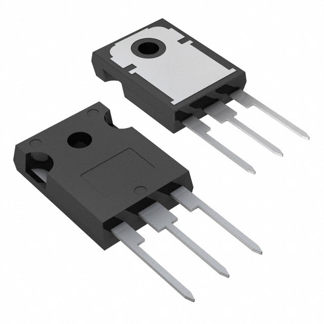
| Mounting Type | Through Hole | - |
| Package / Case | TO-247-3 | - |
Substitute Part Grouping Explanation
Substitution eligibility for the IXGR24N60CD1 is determined by the following critical parameters:
Mandatory Compatibility Criteria:
- Voltage - Collector Emitter Breakdown (Max): 600V minimum
- Current - Collector (Ic) (Max): 42A or greater
- Mounting Type: Through Hole
- Input Type: Standard
Performance Alignment Criteria:
- Operating Temperature Range: -55°C minimum to 150°C or higher
- Gate Charge: Similar range (50–120 nC) for driver compatibility
- Switching characteristics: Td (on/off) within acceptable margins for circuit timing
Package Considerations:
- Primary package: TO-247-3 (direct mechanical compatibility)
- Alternative packages: TO-3P-3 (requires PCB layout verification)
The substitute parts listed below meet or exceed the mandatory criteria and maintain electrical performance within acceptable operating margins for the IXGR24N60CD1 application space.
Parameter Comparison
| Parameter | IXGR24N60CD1 | STGW40H60DLFB | STGW19NC60HD | STGW20V60DF | STGFW20V60DF |
|---|---|---|---|---|---|
| Manufacturer | IXYS | STMicroelectronics | STMicroelectronics | STMicroelectronics | STMicroelectronics |
| Voltage - Collector Emitter Breakdown (Max) | 600V | 600V | 600V | 600V | 600V |
| Current - Collector (Ic) (Max) | 42A | 80A | 42A | 40A | 40A |
| Current - Collector Pulsed (Icm) | 80A | 160A | 60A | 80A | 80A |
| Power - Max | 80W | 283W | 140W | 167W | 52W |
| Vce(on) (Max) @ Vge, Ic | 2.5V @ 15V, 24A | 2V @ 15V, 40A | 2.5V @ 15V, 12A | 2.2V @ 15V, 20A | 2.2V @ 15V, 20A |
| Gate Charge | 55nC | 210nC | 53nC | 116nC | 116nC |
| Td (on/off) @ 25°C | 15ns/75ns | -/142ns | 25ns/97ns | 38ns/149ns | 38ns/149ns |
| Reverse Recovery Time (trr) | 25ns | Not specified | 31ns | 40ns | 40ns |
| Operating Temperature Range | -55 to 150°C | -55 to 175°C | -55 to 150°C | -55 to 175°C | -55 to 175°C |
| Mounting Type | Through Hole | Through Hole | Through Hole | Through Hole | Through Hole |
| Package / Case | TO-247-3 | TO-247-3 | TO-247-3 | TO-247-3 | TO-3P-3 |
| Product Status | Obsolete | Active | Active | Active | Obsolete |
| RoHS Status | Not specified | ROHS3 Compliant | ROHS3 Compliant | ROHS3 Compliant | Not specified |
Engineering Selection Recommendations
Primary Substitutes (Active Product Status):
STGW19NC60HD is the closest functional equivalent to the IXGR24N60CD1. This part maintains identical voltage (600V) and current (42A) ratings, operates within the same temperature range (-55 to 150°C), and is housed in the same TO-247-3 package. Gate charge (53nC) and switching times are comparable to the original part. This substitute is classified as Active product status with ROHS3 compliance, ensuring long-term availability and regulatory alignment.
STGW20V60DF provides an alternative with slightly reduced current rating (40A) but enhanced power dissipation capability (167W vs. 80W). This part operates at an extended temperature range (-55 to 175°C) and maintains TO-247-3 packaging. The Trench Field Stop technology offers improved switching characteristics. This substitute is Active product status with ROHS3 compliance.
Secondary Substitute (Higher Current Capability):
STGW40H60DLFB is suitable for applications requiring higher current capacity (80A) and power handling (283W). This part maintains 600V voltage rating and TO-247-3 packaging but features significantly higher gate charge (210nC) and extended switching times. Use this substitute only when circuit design accommodates increased driver requirements and thermal management capacity.
Not Recommended:
STGFW20V60DF is classified as Obsolete product status. Although electrically compatible, this part does not provide the long-term supply assurance required for production applications. The TO-3P-3 package also requires PCB layout modification compared to the original ISOPLUS247™ footprint.
Frequently Asked Questions (FAQ)
Q: Can STGW19NC60HD directly replace IXGR24N60CD1 without circuit modification?
A: Yes. STGW19NC60HD maintains identical voltage (600V) and current (42A) ratings, operates within the same temperature range, and uses the same TO-247-3 package. Gate charge (53nC) and switching times are comparable, requiring no driver circuit changes.
Q: What is the difference between STGW20V60DF and STGW19NC60HD?
A: STGW20V60DF has a lower current rating (40A vs. 42A) but higher power dissipation (167W vs. 140W) and extended temperature range (-55 to 175°C vs. -55 to 150°C). STGW20V60DF uses Trench Field Stop technology, resulting in higher gate charge (116nC vs. 53nC) and longer switching times. Select STGW19NC60HD for direct replacement; select STGW20V60DF for applications requiring enhanced thermal performance.
Q: Is STGW40H60DLFB suitable for the same application as IXGR24N60CD1?
A: STGW40H60DLFB is electrically compatible but designed for higher current applications (80A vs. 42A). The significantly higher gate charge (210nC vs. 55nC) requires driver circuit verification. Use this part only when the application requires increased current capacity and the driver can supply the higher gate charge.
Q: Why is STGFW20V60DF not recommended as a substitute?
A: STGFW20V60DF is classified as Obsolete product status, which does not provide long-term supply assurance. Additionally, the TO-3P-3 package differs from the original TO-247-3, requiring PCB layout modification. Active alternatives (STGW19NC60HD, STGW20V60DF) are preferred.
Q: What compliance certifications apply to the substitute parts?
A: STGW19NC60HD, STGW20V60DF, and STGW40H60DLFB are ROHS3 compliant. All substitute parts maintain REACH Unaffected status and EAR99 export classification, matching the original part's regulatory profile.
Q: Are there package compatibility considerations when using STGW20V60DF?
A: STGW20V60DF uses TO-247-3 packaging, identical to the original IXGR24N60CD1. No PCB layout modification is required. Thermal management design should account for the higher power dissipation capability (167W vs. 80W).
Q: How do switching times affect circuit performance when substituting?
A: STGW19NC60HD has comparable switching times (25ns/97ns vs. 15ns/75ns), requiring no driver timing adjustments. STGW20V60DF and STGW40H60DLFB have longer switching times (38ns/149ns and -/142ns respectively), which may affect circuit frequency response. Verify driver capability and circuit timing margins before selection.
Alternative Parts

SJ6012L2TP
Littelfuse Inc.
6 Alternative Parts

JMK107BBJ476MA-RE
Taiyo Yuden
10 Alternative Parts

GMK107BBJ475MA-T
Taiyo Yuden
5 Alternative Parts
SJ6020N2ARP
Littelfuse Inc.
3 Alternative Parts
SJ6025R2ATP
Littelfuse Inc.
4 Alternative Parts

2474-05L
API Delevan Inc.
1 Alternative Parts

4590R-684K
API Delevan Inc.
1 Alternative Parts

CM6560R-334
API Delevan Inc.
1 Alternative Parts

CM6460-104
API Delevan Inc.
1 Alternative Parts

5526-12
API Delevan Inc.
1 Alternative Parts