


Request Quote
(Ships tomorrow)
IXGP7N60BD1 IGBT Equivalent & Substitute Parts
Part Overview
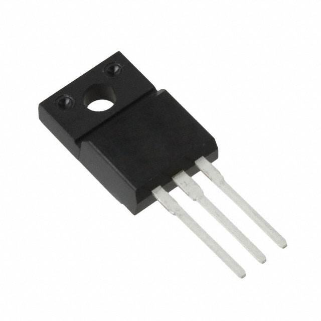
The IXGP7N60BD1 is a 600V, 14A IGBT manufactured by IXYS in the HiPerFAST™ series, housed in a TO-220-3 through-hole package. This component is classified as obsolete, necessitating identification of active equivalent and substitute parts for ongoing design requirements and production continuity. Substitute parts must maintain electrical compatibility within the specified voltage, current, and thermal operating ranges while accommodating packaging and performance variations.
Substiute Parts
Key Parameters
| Parameter | Value | Unit |
|---|---|---|
| Voltage - Collector Emitter Breakdown (Max) | 600 | V |
| Current - Collector (Ic) (Max) | 14 | A |
| Current - Collector Pulsed (Icm) | 56 | A |
| Power - Max | 80 | W |
| Vce(on) (Max) @ Vge, Ic | 2V @ 15V, 7A | V |
| Gate Charge | 25 | nC |
| Switching Energy (off) | 300 | µJ |
| Td (on/off) @ 25°C | 10ns/100ns | ns |
| Reverse Recovery Time (trr) | 35 | ns |
| Operating Temperature Range | -55 to 150 | °C (TJ) |
| Mounting Type | Through Hole | - |
| Package / Case | TO-220-3 | - |
Substitute Part Grouping Explanation
Substitution eligibility for the IXGP7N60BD1 is determined by the following critical parameters:
Mandatory Compatibility Criteria:
- Voltage - Collector Emitter Breakdown: 600V (exact match required)
- Current - Collector (Ic) (Max): minimum 14A
- Mounting Type: Through Hole
- Package / Case: TO-220-3 or compatible TO-220 variants
- Input Type: Standard
Performance Variation Allowances: Substitute parts may exhibit variations in switching energy, gate charge, and thermal characteristics while maintaining the core voltage and current ratings. Power dissipation ratings may differ based on die design and thermal management properties of the specific IGBT technology (standard, Trench Field Stop, or PowerMESH™).
Active Status Requirement: All identified substitutes maintain active product status with current manufacturing availability, ensuring long-term supply chain reliability compared to the obsolete IXGP7N60BD1.
Parameter Comparison
| Parameter | IXGP7N60BD1 | IKA15N60TXKSA1 | STGF7H60DF | STGP7H60DF | STGP7NC60HD |
|---|---|---|---|---|---|
| Manufacturer | IXYS | Infineon Technologies | STMicroelectronics | STMicroelectronics | STMicroelectronics |
| Voltage - Collector Emitter Breakdown (Max) | 600V | 600V | 600V | 600V | 600V |
| Current - Collector (Ic) (Max) | 14A | 14.7A | 14A | 14A | 25A |
| Current - Collector Pulsed (Icm) | 56A | 45A | 28A | 28A | 50A |
| Power - Max | 80W | 35.7W | 24W | 88W | 80W |
| Vce(on) (Max) @ Vge, Ic | 2V @ 15V, 7A | 2.05V @ 15V, 15A | 1.95V @ 15V, 7A | 1.95V @ 15V, 7A | 2.5V @ 15V, 7A |
| Gate Charge | 25nC | 87nC | 46nC | 46nC | 35nC |
| Switching Energy (off) | 300µJ | 570µJ | 100µJ | 100µJ | 115µJ |
| Td (on/off) @ 25°C | 10ns/100ns | 17ns/188ns | 30ns/160ns | 30ns/160ns | 18.5ns/72ns |
| Reverse Recovery Time (trr) | 35ns | 34ns | 136ns | 136ns | 37ns |
| Operating Temperature Range | -55 to 150°C | -40 to 175°C | -55 to 175°C | -55 to 175°C | -55 to 150°C |
| Package / Case | TO-220-3 | TO-220-3 Full Pack | TO-220-3 Full Pack | TO-220-3 | TO-220-3 |
| Product Status | Obsolete | Active | Active | Active | Active |
| RoHS Status | Not specified | ROHS3 Compliant | ROHS3 Compliant | ROHS3 Compliant | ROHS3 Compliant |
Engineering Selection Recommendations
STGP7H60DF (STMicroelectronics)
The STGP7H60DF provides the closest electrical match to the IXGP7N60BD1 with identical 600V/14A ratings and 88W power dissipation. This part is active, RoHS3 compliant, and maintains the same TO-220-3 package footprint. The Trench Field Stop technology delivers lower switching energy (100µJ off vs. 300µJ) and improved thermal performance. Operating temperature range extends to 175°C, exceeding the original specification. This substitute is suitable for direct replacement in applications where the original design parameters are maintained.
STGP7NC60HD (STMicroelectronics)
The STGP7NC60HD offers higher current capability (25A vs. 14A) with identical 600V voltage rating and 80W power dissipation matching the original part. PowerMESH™ technology provides faster switching times (18.5ns/72ns) and lower gate charge (35nC). This part is active, RoHS3 compliant, and maintains TO-220-3 packaging. Selection of this part is appropriate for applications requiring enhanced current margin or improved switching performance within the same thermal envelope.
IKA15N60TXKSA1 (Infineon Technologies)
The IKA15N60TXKSA1 delivers 600V/14.7A ratings with Trench Field Stop technology. This part is active and RoHS3 compliant. The higher gate charge (87nC) and switching energy (570µJ) indicate different drive characteristics compared to the original part. Operating temperature extends to 175°C. This substitute is applicable where Infineon component qualification is required or where the extended temperature range provides system benefit.
STGF7H60DF (STMicroelectronics)
The STGF7H60DF maintains 600V/14A electrical ratings with the lowest power dissipation (24W) among substitutes. Trench Field Stop technology and RoHS3 compliance are provided. The TO-220FP package variant requires verification of mechanical compatibility with existing PCB layouts. This part is suitable for applications where thermal management is constrained or where lower power dissipation is advantageous.
Frequently Asked Questions (FAQ)
Q: Can the STGP7H60DF directly replace the IXGP7N60BD1 without circuit modifications?
A: The STGP7H60DF maintains identical voltage (600V) and current (14A) ratings with compatible TO-220-3 packaging. Electrical substitution is direct. However, the lower switching energy (100µJ vs. 300µJ) and different gate charge (46nC vs. 25nC) may require gate drive circuit verification to confirm adequate drive capability and switching performance alignment with the original design.
Q: What is the primary difference between the STGP7H60DF and STGP7NC60HD?
A: Both parts are STMicroelectronics 600V IGBTs in TO-220-3 packages. The STGP7NC60HD provides higher collector current (25A vs. 14A) and uses PowerMESH™ technology with faster switching times (18.5ns/72ns vs. 30ns/160ns). The STGP7H60DF uses Trench Field Stop technology. Selection depends on whether increased current capacity or faster switching performance is required.
Q: Is the IKA15N60TXKSA1 suitable for applications requiring the original IXGP7N60BD1 specifications?
A: The IKA15N60TXKSA1 meets the 600V voltage and 14.7A current requirements. However, the significantly higher gate charge (87nC vs. 25nC) and switching energy (570µJ vs. 300µJ) indicate different drive characteristics. Gate drive circuit compatibility must be verified before substitution.
Q: Why does the STGF7H60DF use a TO-220FP package variant instead of standard TO-220-3?
A: The TO-220FP is a full-pack variant of the TO-220-3 package family. Both provide the same three-terminal through-hole configuration and pin spacing. PCB layout compatibility should be confirmed, as the full-pack variant may have different mechanical dimensions or mounting requirements.
Q: Are all substitute parts RoHS3 compliant?
A: All identified substitute parts (IKA15N60TXKSA1, STGF7H60DF, STGP7H60DF, and STGP7NC60HD) are RoHS3 compliant. The original IXGP7N60BD1 RoHS status is not specified in the provided data.
Q: What is the impact of different operating temperature ranges on part selection?
A: The IXGP7N60BD1 operates from -55°C to 150°C. The STGP7H60DF, STGF7H60DF, and IKA15N60TXKSA1 extend the upper limit to 175°C, providing additional thermal margin. The STGP7NC60HD maintains the 150°C upper limit. Selection should align with the application's thermal requirements and system design margins.
Q: Can the STGP7NC60HD be used in applications designed for 14A operation?
A: The STGP7NC60HD is rated for 25A continuous collector current, exceeding the 14A requirement. This part operates within specification at 14A with improved current margin. The higher Vce(on) (2.5V vs. 2V at 7A) results in slightly increased power dissipation at equivalent operating points. Thermal analysis should confirm acceptable junction temperature under the application's duty cycle.
Alternative Parts

SJ6012L2TP
Littelfuse Inc.
6 Alternative Parts

JMK107BBJ476MA-RE
Taiyo Yuden
10 Alternative Parts

GMK107BBJ475MA-T
Taiyo Yuden
5 Alternative Parts
SJ6020N2ARP
Littelfuse Inc.
3 Alternative Parts
SJ6025R2ATP
Littelfuse Inc.
4 Alternative Parts

2474-05L
API Delevan Inc.
1 Alternative Parts

4590R-684K
API Delevan Inc.
1 Alternative Parts

CM6560R-334
API Delevan Inc.
1 Alternative Parts

CM6460-104
API Delevan Inc.
1 Alternative Parts

5526-12
API Delevan Inc.
1 Alternative Parts