


Request Quote
(Ships tomorrow)
IXGH60N60C2 IGBT Equivalent & Substitute Parts
Part Overview
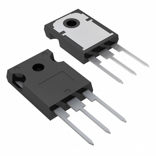
The IXGH60N60C2 is a 600V, 75A IGBT manufactured by IXYS in the HiPerFAST™ series, housed in a TO-247AD package. This component is classified as Obsolete, indicating that direct procurement from the original manufacturer may be limited or unavailable. The part delivers 480W maximum power dissipation with a Punch-Through (PT) IGBT architecture optimized for high-frequency switching applications. Identifying equivalent and substitute parts is necessary to maintain design continuity, ensure supply chain reliability, and support ongoing production requirements for systems utilizing this component.
Substiute Parts
Key Parameters
| Parameter | Value | Unit |
|---|---|---|
| Voltage - Collector Emitter Breakdown (Max) | 600 | V |
| Current - Collector (Ic) (Max) | 75 | A |
| Current - Collector Pulsed (Icm) | 300 | A |
| Power - Max | 480 | W |
| Vce(on) (Max) @ Vge, Ic | 2.5V @ 15V, 50A | V |
| Gate Charge | 146 | nC |
| Switching Energy (off) | 480 | µJ |
| Td (on/off) @ 25°C | 18ns/95ns | ns |
| Operating Temperature Range | -55 to 150 | °C (TJ) |
| Package / Case | TO-247-3 | - |
| Mounting Type | Through Hole | - |
Substitute Part Grouping Explanation
Substitution of the IXGH60N60C2 is determined by strict alignment of electrical and mechanical parameters within the IGBT transistor category. The following criteria establish substitution validity:
Primary Substitution Criteria:
- Voltage rating: Minimum 600V collector-emitter breakdown voltage (equal or higher)
- Current rating: Minimum 75A continuous collector current (equal or higher)
- Package compatibility: TO-247-3 through-hole mounting
- Input type: Standard gate drive configuration
- Operating temperature range: Minimum -55°C to 150°C junction temperature capability
Secondary Alignment Parameters:
- Vce(on) saturation voltage at rated conditions
- Gate charge characteristics
- Switching energy (on/off) performance
- Pulsed current capability (Icm)
Four substitute parts meet these criteria with varying degrees of parameter alignment and product status differentiation.
Parameter Comparison
| Parameter | IXGH60N60C2 (Main) | FGH40N60SMD-F085 | HGTG40N60A4 | NGTB40N60L2WG | STGW60H65FB |
|---|---|---|---|---|---|
| Manufacturer | IXYS | onsemi | onsemi | onsemi | STMicroelectronics |
| Voltage - Collector Emitter Breakdown (Max) | 600V | 600V | 600V | 600V | 650V |
| Current - Collector (Ic) (Max) | 75A | 80A | 75A | 80A | 80A |
| Current - Collector Pulsed (Icm) | 300A | 120A | 300A | 160A | 240A |
| Power - Max | 480W | 349W | 625W | 417W | 375W |
| Vce(on) (Max) @ Vge, Ic | 2.5V @ 15V, 50A | 2.5V @ 15V, 40A | 2.7V @ 15V, 40A | 2.61V @ 15V, 40A | 2.3V @ 15V, 60A |
| Gate Charge | 146nC | 180nC | 350nC | 228nC | 306nC |
| Switching Energy (off) | 480µJ | 300µJ | 370µJ | 280µJ | 626µJ |
| Td (on/off) @ 25°C | 18ns/95ns | 18ns/110ns | 25ns/145ns | 98ns/213ns | 51ns/160ns |
| Operating Temperature Range | -55 to 150°C | -55 to 175°C | -55 to 150°C | -55 to 175°C | -55 to 175°C |
| Package / Case | TO-247-3 | TO-247-3 | TO-247-3 | TO-247-3 | TO-247-3 |
| Product Status | Obsolete | Active | Obsolete | Obsolete | Active |
| IGBT Type | PT (Punch-Through) | Field Stop | - | Trench Field Stop | Trench Field Stop |
Engineering Selection Recommendations
FGH40N60SMD-F085 (onsemi)
This substitute provides the closest electrical alignment to the IXGH60N60C2 with 80A continuous current capability and 600V voltage rating. The part is classified as Active, ensuring ongoing availability and supply chain support. It carries AEC-Q101 automotive qualification and ROHS3 compliance. The switching energy profile (300µJ off) is superior to the main part, reducing switching losses. The extended operating temperature range (-55°C to 175°C) provides thermal margin beyond the original specification. This part is suitable for direct substitution in applications where the lower pulsed current rating (120A versus 300A) does not constrain system performance.
HGTG40N60A4 (onsemi)
This substitute matches the IXGH60N60C2 in continuous current (75A) and voltage rating (600V), with identical pulsed current capability (300A). However, the part is classified as Obsolete, limiting long-term supply reliability. The higher gate charge (350nC) and extended switching delays (25ns/145ns) indicate slower switching characteristics compared to the main part. The higher power rating (625W) provides thermal headroom. This part is suitable only when supply continuity is not a primary concern or when existing inventory is available.
NGTB40N60L2WG (onsemi)
This substitute meets the 600V voltage and 80A current requirements with Trench Field Stop architecture. The part is classified as Obsolete, presenting supply chain limitations. The significantly extended switching delays (98ns/213ns) and higher gate charge (228nC) indicate substantially slower switching performance compared to the IXGH60N60C2. The lower pulsed current rating (160A) and reduced power dissipation (417W) may constrain high-frequency or high-current pulse applications. This part is suitable only for applications with relaxed switching speed requirements and where supply inventory is confirmed.
STGW60H65FB (STMicroelectronics)
This substitute provides the highest voltage rating (650V) and maintains 80A continuous current capability. The part is classified as Active, ensuring reliable long-term availability and supply chain support. ROHS3 compliance is confirmed. The extended operating temperature range (-55°C to 175°C) exceeds the original specification. The switching energy profile (626µJ off) is higher than the main part, indicating increased switching losses. The lower Vce(on) (2.3V at 60A) provides improved conduction efficiency. This part is suitable for applications where the higher voltage rating provides system margin and where increased switching losses are acceptable.
Frequently Asked Questions (FAQ)
Q: Can the FGH40N60SMD-F085 directly replace the IXGH60N60C2 in existing designs?
A: The FGH40N60SMD-F085 meets the primary electrical requirements (600V, 80A) and shares the TO-247-3 package. However, the pulsed current rating is reduced from 300A to 120A. Direct substitution is valid only if the application does not require pulsed current operation exceeding 120A. Gate drive timing differences (18ns/110ns versus 18ns/95ns) are minimal and do not typically require circuit redesign.
Q: Why is the STGW60H65FB rated at 650V instead of 600V?
A: The higher voltage rating (650V) provides additional design margin and system reliability. A 650V-rated device can be used in 600V applications without performance degradation. The higher rating does not create compatibility issues and may improve long-term reliability in applications subject to voltage transients or overshoot conditions.
Q: What is the significance of the IGBT Type differences (PT, Field Stop, Trench Field Stop)?
A: IGBT architecture affects switching speed, conduction losses, and thermal characteristics. The IXGH60N60C2 uses Punch-Through (PT) architecture with fast switching (18ns/95ns). Field Stop and Trench Field Stop variants offer different trade-offs between switching speed and conduction losses. Substitution with different architectures is valid if the application tolerates the resulting switching energy and delay changes.
Q: Are the Obsolete-status parts suitable for new production designs?
A: Parts classified as Obsolete (HGTG40N60A4, NGTB40N60L2WG) present supply chain risk for new production. These parts are suitable only for maintenance, repair, or low-volume applications where existing inventory is confirmed available. For new designs, Active-status parts (FGH40N60SMD-F085, STGW60H65FB) are recommended to ensure long-term supply continuity.
Q: How do gate charge differences affect circuit design?
A: Gate charge (146nC for IXGH60N60C2 versus 180-350nC for substitutes) determines the gate drive current and switching speed. Higher gate charge requires increased gate drive power and may extend switching delays. Substitutes with higher gate charge (HGTG40N60A4 at 350nC, STGW60H65FB at 306nC) may require gate drive circuit optimization to maintain switching performance. The FGH40N60SMD-F085 (180nC) requires minimal gate drive adjustment.
Q: What is the impact of operating temperature range differences?
A: The IXGH60N60C2 operates to 150°C junction temperature. Substitutes with extended ranges (-55°C to 175°C) provide additional thermal margin. This does not create compatibility issues; the device simply tolerates higher temperatures. Applications operating near the 150°C limit benefit from substitutes with 175°C ratings.
Q: Is the TO-247-3 package identical across all substitute parts?
A: All substitute parts use TO-247-3 through-hole packages, ensuring mechanical compatibility with existing PCB layouts and heatsink mounting. The IXGH60N60C2 uses TO-247AD designation, which is functionally equivalent to TO-247-3. No PCB redesign is required for package substitution.
Alternative Parts

SJ6012L2TP
Littelfuse Inc.
6 Alternative Parts

JMK107BBJ476MA-RE
Taiyo Yuden
10 Alternative Parts

GMK107BBJ475MA-T
Taiyo Yuden
5 Alternative Parts
SJ6020N2ARP
Littelfuse Inc.
3 Alternative Parts
SJ6025R2ATP
Littelfuse Inc.
4 Alternative Parts

2474-05L
API Delevan Inc.
1 Alternative Parts

4590R-684K
API Delevan Inc.
1 Alternative Parts

CM6560R-334
API Delevan Inc.
1 Alternative Parts

CM6460-104
API Delevan Inc.
1 Alternative Parts

5526-12
API Delevan Inc.
1 Alternative Parts