


Request Quote
(Ships tomorrow)
IXFY5N50P3 Equivalent & Substitute Parts
Part Overview
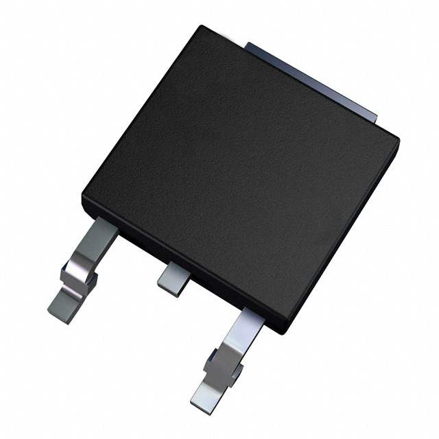
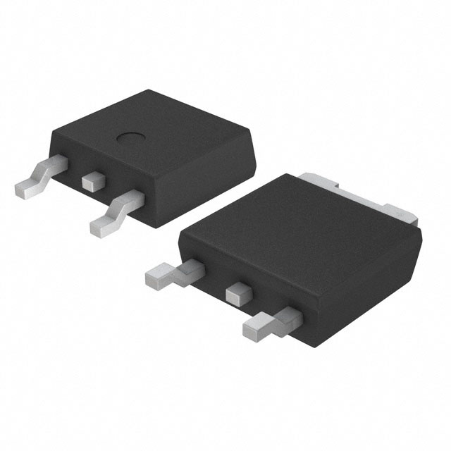
The IXFY5N50P3 is an N-Channel MOSFET rated for 500V drain-to-source voltage with 5A continuous drain current in a surface mount TO-252AA (DPAK) package. Manufactured by IXYS as part of the HiPerFET™ and Polar3™ series, this device is classified as obsolete. Due to its obsolete status and limited availability for new production cycles, identifying equivalent substitute components is necessary to maintain design continuity and ensure long-term supply chain reliability.
Substiute Parts
Key Parameters
| Parameter | Value | Unit |
|---|---|---|
| FET Type | N-Channel | — |
| Technology | MOSFET (Metal Oxide) | — |
| Drain to Source Voltage (Vdss) | 500 | V |
| Continuous Drain Current (Id) @ 25°C | 5 | A |
| Drive Voltage (Max Rds On) | 10 | V |
| Rds On (Max) @ Id, Vgs | 1.65 | Ohm @ 2.5A, 10V |
| Gate Charge (Qg) (Max) @ Vgs | 6.9 | nC @ 10V |
| Power Dissipation (Max) | 114 | W |
| Operating Temperature Range | -55 to 150 | °C (TJ) |
| Package Type | TO-252-3, DPAK (2 Leads + Tab) | — |
| RoHS Status | ROHS3 Compliant | — |
| Moisture Sensitivity Level | 1 (Unlimited) | — |
Substitute Part Grouping Explanation
Substitution of the IXFY5N50P3 is determined by the following critical electrical and mechanical parameters:
Primary Substitution Criteria:
- Drain-to-Source Voltage (Vdss) rating must equal or exceed 500V
- Continuous Drain Current (Id) must equal or exceed 5A at 25°C
- Package type must be TO-252-3 (DPAK) for mechanical compatibility
- Operating temperature range must encompass -55°C to 150°C
- RoHS3 compliance and MSL 1 rating required for regulatory alignment
Secondary Compatibility Factors:
- Gate charge (Qg) and input capacitance (Ciss) affect switching performance
- On-resistance (Rds On) impacts thermal performance and power dissipation
- Gate threshold voltage (Vgs(th)) and maximum gate voltage (Vgs Max) determine drive circuit compatibility
The substitute parts listed below meet the primary criteria with variations in secondary parameters that reflect different manufacturing technologies and design approaches within the 500V N-Channel MOSFET category.
Parameter Comparison
| Parameter | IXFY5N50P3 | IRFR825TRPBF | IRFR320TRLPBF | Unit |
|---|---|---|---|---|
| Manufacturer | IXYS | Infineon Technologies | Vishay Siliconix | — |
| FET Type | N-Channel | N-Channel | N-Channel | — |
| Vdss | 500 | 500 | 400 | V |
| Id @ 25°C | 5 | 6 | 3.1 | A |
| Drive Voltage | 10 | 10 | 10 | V |
| Rds On (Max) @ Id, Vgs | 1.65 @ 2.5A, 10V | 1.3 @ 3.7A, 10V | 1.8 @ 1.9A, 10V | Ohm |
| Qg (Max) @ Vgs | 6.9 @ 10V | 34 @ 10V | 20 @ 10V | nC |
| Ciss (Max) @ Vds | 370 @ 25V | 1346 @ 25V | 350 @ 25V | pF |
| Vgs(th) (Max) @ Id | 5 @ 1mA | 5 @ 250µA | 4 @ 250µA | V |
| Vgs (Max) | ±30 | ±20 | ±20 | V |
| Power Dissipation (Max) | 114 | 119 | 42 | W |
| Operating Temperature | -55 to 150 | -55 to 150 | -55 to 150 | °C (TJ) |
| Package | TO-252-3 (DPAK) | TO-252-3 (DPAK) | TO-252-3 (DPAK) | — |
| Product Status | Obsolete | Not For New Designs | Active | — |
| RoHS Status | ROHS3 Compliant | ROHS3 Compliant | ROHS3 Compliant | — |
| MSL | 1 (Unlimited) | 1 (Unlimited) | 1 (Unlimited) | — |
Engineering Selection Recommendations
IRFR825TRPBF (Infineon Technologies)
The IRFR825TRPBF provides the closest electrical match to the IXFY5N50P3, with identical 500V Vdss rating and superior continuous drain current (6A vs. 5A). Power dissipation capability is equivalent (119W vs. 114W). This device maintains full TO-252-3 package compatibility and operates across the same temperature range. However, the IRFR825TRPBF carries a "Not For New Designs" status, indicating Infineon has transitioned this product line. RoHS3 compliance and MSL 1 rating are maintained. The higher gate charge (34 nC vs. 6.9 nC) and input capacitance (1346 pF vs. 370 pF) require evaluation against drive circuit specifications.
IRFR320TRLPBF (Vishay Siliconix)
The IRFR320TRLPBF is classified as Active, providing the most favorable long-term availability and supply chain stability. This device maintains full TO-252-3 package compatibility and operates across the required temperature range with RoHS3 compliance and MSL 1 rating. However, the 400V Vdss rating is 100V lower than the IXFY5N50P3, and continuous drain current is reduced to 3.1A. Power dissipation capability is significantly lower (42W vs. 114W). This substitute is suitable only for applications where the 500V voltage rating is not a critical design requirement and where the reduced current and power handling capacity align with circuit specifications.
Selection Basis:
For applications requiring the full 500V rating and 5A+ current capability, the IRFR825TRPBF is the appropriate substitute despite its "Not For New Designs" status. For new designs or applications with reduced voltage and current requirements, the IRFR320TRLPBF offers superior long-term availability as an Active product. All three devices maintain regulatory compliance and identical thermal operating ranges.
Frequently Asked Questions (FAQ)
Q: Can the IRFR320TRLPBF directly replace the IXFY5N50P3 in all applications?
A: No. The IRFR320TRLPBF has a 400V Vdss rating compared to the IXFY5N50P3's 500V rating. Direct substitution is only valid for applications where the maximum operating voltage does not exceed 400V. Additionally, the reduced continuous drain current (3.1A vs. 5A) and power dissipation (42W vs. 114W) must be verified against circuit requirements.
Q: What is the significance of the "Not For New Designs" status on the IRFR825TRPBF?
A: This status indicates that Infineon has discontinued active development and marketing of this product line. While the device remains available and functional, the manufacturer recommends using alternative products for new design projects. Existing designs using this part may continue operation, but long-term availability cannot be guaranteed.
Q: Are all three devices pin-compatible?
A: Yes. All three devices use the TO-252-3 (DPAK) package with identical pin configuration: Gate, Drain, and Source (with Source connected to the tab). Physical and electrical pin compatibility is maintained across all substitutes.
Q: How do the gate charge differences affect circuit design?
A: The IXFY5N50P3 has a gate charge of 6.9 nC, while the IRFR825TRPBF has 34 nC. Higher gate charge requires more current from the gate drive circuit to achieve the same switching speed. Drive circuits must be evaluated to ensure adequate gate current capacity. The IRFR320TRLPBF's 20 nC gate charge represents an intermediate value.
Q: What is the impact of the higher input capacitance in the IRFR825TRPBF?
A: The IRFR825TRPBF has an input capacitance (Ciss) of 1346 pF compared to 370 pF in the IXFY5N50P3. Higher input capacitance increases the charge required to drive the gate and may affect switching frequency performance. Gate drive circuit design must account for this increased capacitive load.
Q: Are all three devices RoHS3 compliant?
A: Yes. All three devices carry RoHS3 compliance certification and MSL 1 (Unlimited) moisture sensitivity rating, meeting current regulatory requirements for electronic component manufacturing and assembly.
Q: Which substitute offers the best long-term supply chain availability?
A: The IRFR320TRLPBF carries an Active product status, indicating ongoing manufacturing and distribution support from Vishay Siliconix. This provides the most favorable long-term availability. However, its reduced voltage and current ratings limit its applicability as a direct substitute for the IXFY5N50P3.
Alternative Parts

SJ6012L2TP
Littelfuse Inc.
6 Alternative Parts

JMK107BBJ476MA-RE
Taiyo Yuden
10 Alternative Parts

GMK107BBJ475MA-T
Taiyo Yuden
5 Alternative Parts
SJ6020N2ARP
Littelfuse Inc.
3 Alternative Parts
SJ6025R2ATP
Littelfuse Inc.
4 Alternative Parts

2474-05L
API Delevan Inc.
1 Alternative Parts

4590R-684K
API Delevan Inc.
1 Alternative Parts

CM6560R-334
API Delevan Inc.
1 Alternative Parts

CM6460-104
API Delevan Inc.
1 Alternative Parts

5526-12
API Delevan Inc.
1 Alternative Parts