


Request Quote
(Ships tomorrow)
IXFR80N60P3 Equivalent & Substitute Parts
Part Overview
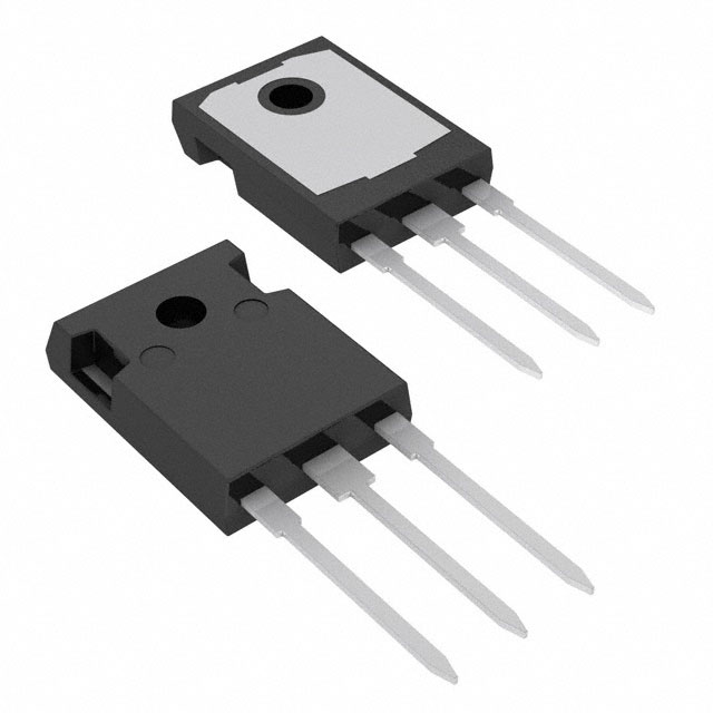
The IXFR80N60P3 is an N-Channel 600V 48A MOSFET manufactured by IXYS in the HiPerFET™ and Polar3™ series. This device is housed in an ISOPLUS247™ package and rated for 540W power dissipation at case temperature. The part is currently Active in product status and fully compliant with RoHS3 and REACH regulations.
Substitute parts are necessary when the IXFR80N60P3 becomes unavailable, when design requirements shift toward higher current capacity or improved thermal performance, or when alternative manufacturers' components offer superior specifications within the same voltage and package class.
Substiute Parts
Key Parameters
| Parameter | Value | Unit |
|---|---|---|
| Drain to Source Voltage (Vdss) | 600 | V |
| Continuous Drain Current (Id) @ 25°C | 48 | A |
| On-State Resistance (Rds On) @ 40A, 10V | 76 | mOhm |
| Gate Threshold Voltage (Vgs(th)) @ 8mA | 5 | V |
| Gate Charge (Qg) @ 10V | 190 | nC |
| Input Capacitance (Ciss) @ 25V | 13100 | pF |
| Power Dissipation (Max) | 540 | W |
| Operating Temperature Range | -55 to 150 | °C |
| Package Type | TO-247-3 | - |
| Mounting Type | Through Hole | - |
Substitute Part Grouping Explanation
Substitution of the IXFR80N60P3 is determined by the following critical parameters:
Voltage Class: All substitute parts must maintain a Drain to Source Voltage (Vdss) rating of 600V or higher to ensure safe operation in the same circuit topology.
Current Rating: Substitute parts must support a continuous drain current (Id) of 48A or greater at 25°C to handle the same load without thermal stress.
Package Compatibility: All substitutes must use the TO-247-3 through-hole package to ensure mechanical and thermal interface compatibility with existing PCB layouts and heatsinks.
On-State Resistance (Rds On): Lower Rds On values indicate improved efficiency and reduced power dissipation. Substitutes with Rds On values at or below 76mOhm @ rated conditions are preferred.
Operating Temperature Range: All substitutes must support the full -55°C to 150°C operating range.
Regulatory Compliance: All substitutes must be RoHS3 compliant and REACH unaffected to meet environmental and safety standards.
Substitute parts are grouped into two categories: Direct Substitutes (matching or exceeding all key parameters) and Functional Alternatives (meeting voltage and package requirements with trade-offs in current capacity or power dissipation).
Parameter Comparison
| Manufacturer Part Number | Manufacturer | Vdss (V) | Id @ 25°C (A) | Rds On (mOhm) | Qg (nC) | Power Dissipation (W) | Product Status | Package |
|---|---|---|---|---|---|---|---|---|
| IXFR80N60P3 | IXYS | 600 | 48 | 76 | 190 | 540 | Active | TO-247-3 |
| FCH104N60 | onsemi | 600 | 37 | 104 | 82 | 357 | Obsolete | TO-247-3 |
| FCH104N60F-F085 | onsemi | 600 | 37 | 104 | 139 | 357 | Not For New Designs | TO-247-3 |
| FCH47N60-F085 | onsemi | 600 | 47 | 79 | 250 | 417 | Not For New Designs | TO-247-3 |
| IPW60R070C6FKSA1 | Infineon Technologies | 600 | 53 | 70 | 170 | 391 | Not For New Designs | TO-247-3 |
| IPW60R070CFD7XKSA1 | Infineon Technologies | 650 | 31 | 70 | 67 | 156 | Active | TO-247-3 |
| IPW60R075CPFKSA1 | Infineon Technologies | 650 | 39 | 75 | 116 | 313 | Not For New Designs | TO-247-3 |
| IPW60R080P7XKSA1 | Infineon Technologies | 600 | 37 | 80 | 51 | 129 | Active | TO-247-3 |
| IPW65R095C7XKSA1 | Infineon Technologies | 650 | 24 | 95 | 45 | 128 | Active | TO-247-3 |
| R6046FNZ1C9 | Rohm Semiconductor | 600 | 46 | 98 | 150 | 120 | Obsolete | TO-247-3 |
| SPW55N80C3FKSA1 | Infineon Technologies | 800 | 54.9 | 85 | 288 | 500 | Active | TO-247-3 |
Engineering Selection Recommendations
Direct Substitutes (Recommended for New Designs):
IPW60R070C6FKSA1 (Infineon Technologies) is the closest functional equivalent. It exceeds the IXFR80N60P3 in continuous drain current (53A vs. 48A) and offers superior on-state resistance (70mOhm vs. 76mOhm), resulting in lower power dissipation and improved thermal performance. However, this part is marked "Not For New Designs," limiting its use to legacy system maintenance.
IPW60R080P7XKSA1 (Infineon Technologies, CoolMOS™ P7 series) is an Active product suitable for new designs. While it carries a lower continuous drain current rating (37A vs. 48A), it provides significantly lower gate charge (51nC vs. 190nC) and reduced power dissipation (129W vs. 540W), making it suitable for applications where switching speed and efficiency are prioritized over maximum current capacity.
SPW55N80C3FKSA1 (Infineon Technologies, CoolMOS™ C3 series) is an Active product with higher voltage rating (800V vs. 600V) and superior current capacity (54.9A vs. 48A). This part is suitable for applications requiring higher voltage headroom or increased current margin, though the higher voltage rating may introduce unnecessary cost in 600V-class designs.
Functional Alternatives (Legacy Applications):
FCH47N60-F085 (onsemi, SuperFET™ series) provides near-equivalent current capacity (47A vs. 48A) and comparable on-state resistance (79mOhm vs. 76mOhm). This part is marked "Not For New Designs" and carries AEC-Q101 automotive qualification, making it suitable only for replacement in existing automotive applications.
IPW60R075CPFKSA1 (Infineon Technologies, CoolMOS™ series) offers 39A continuous current with 75mOhm on-state resistance. This part is marked "Not For New Designs" and is suitable for legacy system support only.
Parts Not Recommended:
FCH104N60 and FCH104N60F-F085 (onsemi) fall below the required current specification (37A vs. 48A) and exhibit higher on-state resistance (104mOhm vs. 76mOhm). These parts are obsolete or not recommended for new designs.
IPW60R070CFD7XKSA1 (Infineon Technologies, CoolMOS™ CFD7 series) is Active but rated for only 31A continuous current, insufficient for direct substitution.
IPW65R095C7XKSA1 (Infineon Technologies, CoolMOS™ series) is rated for only 24A continuous current and is unsuitable for this application.
R6046FNZ1C9 (Rohm Semiconductor) is obsolete and rated for only 46A continuous current with higher on-state resistance (98mOhm vs. 76mOhm).
Frequently Asked Questions (FAQ)
Q: Can I use IPW60R070C6FKSA1 as a direct replacement for IXFR80N60P3?
A: IPW60R070C6FKSA1 meets all electrical requirements and exceeds current capacity (53A vs. 48A) and on-state resistance specifications. However, it is marked "Not For New Designs," restricting its use to legacy system maintenance and repair only. For new designs, use IPW60R080P7XKSA1 or SPW55N80C3FKSA1.
Q: What is the difference between ISOPLUS247™ and TO-247-3 packages?
A: ISOPLUS247™ is IXYS's proprietary designation for the TO-247-3 package. Both refer to the same three-lead through-hole package with identical mechanical and thermal interfaces. All listed substitutes use the standard TO-247-3 package and are mechanically compatible with ISOPLUS247™ footprints.
Q: Why does IPW60R080P7XKSA1 have lower power dissipation than IXFR80N60P3?
A: IPW60R080P7XKSA1 is rated at 129W maximum power dissipation compared to IXFR80N60P3's 540W. This difference reflects the test conditions and thermal measurement methodology used by each manufacturer. The lower gate charge (51nC vs. 190nC) indicates faster switching characteristics, which reduces switching losses in high-frequency applications.
Q: Can I use SPW55N80C3FKSA1 in a 600V circuit?
A: Yes. SPW55N80C3FKSA1 is rated for 800V Drain to Source Voltage, which exceeds the 600V requirement. The higher voltage rating provides additional safety margin but does not affect operation in 600V circuits. Verify that the circuit topology and PCB layout accommodate the different pin configuration if applicable.
Q: Are all substitute parts RoHS3 compliant?
A: Yes. All listed substitute parts are RoHS3 compliant and REACH unaffected, meeting current environmental and regulatory requirements.
Q: What is the significance of "Not For New Designs" status?
A: Parts marked "Not For New Designs" are in end-of-life phase and may have limited availability or extended lead times. These parts are suitable only for replacement in existing systems or legacy applications. For new product development, use only parts marked "Active" in product status.
Q: How do I determine which substitute is best for my application?
A: Selection depends on application requirements. For maximum current capacity and efficiency, use IPW60R070C6FKSA1 (if legacy support is acceptable) or SPW55N80C3FKSA1 (for new designs with higher voltage margin). For switching speed and reduced gate charge, use IPW60R080P7XKSA1. For automotive applications, use FCH47N60-F085 if AEC-Q101 qualification is required.
Q: What is gate charge (Qg) and why does it matter?
A: Gate charge is the total charge required to switch the MOSFET from off to on state. Lower gate charge reduces switching losses and allows faster switching frequencies. IXFR80N60P3 has 190nC gate charge, while IPW60R080P7XKSA1 has only 51nC, making the latter more efficient in high-frequency switching applications.
Q: Can I parallel multiple substitute MOSFETs to increase current capacity?
A: Paralleling MOSFETs is possible but requires careful circuit design to ensure equal current distribution. Differences in on-state resistance (Rds On) and gate threshold voltage (Vgs(th)) between devices can cause unequal current sharing. Consult the MOSFET manufacturer's paralleling guidelines before implementing this approach.
Alternative Parts

SJ6012L2TP
Littelfuse Inc.
6 Alternative Parts

JMK107BBJ476MA-RE
Taiyo Yuden
10 Alternative Parts

GMK107BBJ475MA-T
Taiyo Yuden
5 Alternative Parts
SJ6020N2ARP
Littelfuse Inc.
3 Alternative Parts
SJ6025R2ATP
Littelfuse Inc.
4 Alternative Parts

2474-05L
API Delevan Inc.
1 Alternative Parts

4590R-684K
API Delevan Inc.
1 Alternative Parts

CM6560R-334
API Delevan Inc.
1 Alternative Parts

CM6460-104
API Delevan Inc.
1 Alternative Parts

5526-12
API Delevan Inc.
1 Alternative Parts