


Request Quote
(Ships tomorrow)
IXFP230N075T2 Equivalent & Substitute Parts
Part Overview
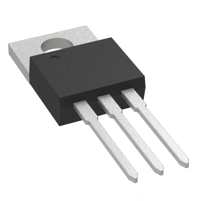
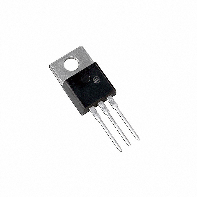
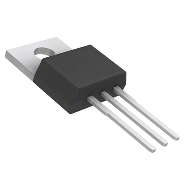
The IXFP230N075T2 is an N-Channel MOSFET manufactured by IXYS, designed for high-current switching applications. This device operates at 75V drain-to-source voltage with a continuous drain current rating of 230A at 25°C case temperature, housed in a TO-220-3 through-hole package. The part belongs to the HiPerFET™ and TrenchT2™ series and maintains Active product status with full RoHS3 compliance.
Substitute parts are necessary when the primary device becomes unavailable, when inventory constraints require alternative sourcing, or when design flexibility permits operation within the electrical and mechanical parameters of equivalent devices. Substitution must maintain compatibility across voltage rating, current capacity, package type, and thermal characteristics.
Substiute Parts
Key Parameters
| Parameter | Value | Unit |
|---|---|---|
| Drain to Source Voltage (Vdss) | 75 | V |
| Continuous Drain Current (Id) @ 25°C | 230 | A (Tc) |
| On-State Resistance (Rds On) @ 50A, 10V | 4.2 | mOhm |
| Gate Threshold Voltage (Vgs(th)) @ 1mA | 4 | V |
| Gate Charge (Qg) @ 10V | 178 | nC |
| Input Capacitance (Ciss) @ 25V | 10500 | pF |
| Power Dissipation (Max) | 480 | W (Tc) |
| Operating Temperature Range | -55 to 175 | °C (TJ) |
| Package Type | TO-220-3 | Through Hole |
| FET Type | N-Channel | — |
Substitute Part Grouping Explanation
Substitution eligibility for the IXFP230N075T2 is determined by the following critical parameters:
Voltage Rating Compatibility: The drain-to-source voltage (Vdss) must equal or exceed 75V. Devices rated below 75V cannot be substituted as they lack adequate voltage headroom for the application.
Current Capacity: The continuous drain current (Id) at 25°C case temperature must support the application requirements. While the primary device is rated at 230A, substitute devices with lower current ratings remain valid if the application does not demand the full 230A capacity.
Package and Mounting: All substitute devices must use TO-220-3 through-hole packaging to ensure mechanical and thermal compatibility with existing PCB layouts and heatsinking arrangements.
Temperature Range: Operating temperature range must span -55°C to 175°C (TJ) to maintain functional equivalence across the full operating envelope.
Gate Drive Voltage: Maximum gate-source voltage (Vgs Max) must be ±20V to ensure compatibility with existing gate drive circuits.
On-State Resistance: Rds On characteristics must be comparable to support similar power dissipation profiles and thermal management strategies.
Substitute devices are grouped into two categories: Direct Voltage Equivalents (75V rated) and Lower Voltage Alternatives (60V rated). Lower voltage alternatives are suitable only when the application circuit design permits operation at reduced voltage ratings.
Parameter Comparison
| Parameter | IXFP230N075T2 | FDP047N08-F102 | IRFB3207ZPBF | CSD18532KCS | FDP050AN06A0 | IRFB3306PBF | PSMN3R9-60PSQ |
|---|---|---|---|---|---|---|---|
| Manufacturer | IXYS | onsemi | Infineon Technologies | Texas Instruments | onsemi | Infineon Technologies | Nexperia USA Inc. |
| Vdss (V) | 75 | 75 | 75 | 60 | 60 | 60 | 60 |
| Id @ 25°C (A) | 230 | 164 | 120 | 100 | 80 (Tc) | 120 | 130 |
| Rds On (mOhm) | 4.2 @ 50A, 10V | 4.7 @ 80A, 10V | 4.1 @ 75A, 10V | 4.2 @ 100A, 10V | 5 @ 80A, 10V | 4.2 @ 75A, 10V | 3.9 @ 25A, 10V |
| Vgs(th) (V) | 4 @ 1mA | 4.5 @ 250µA | 4 @ 150µA | 2.2 @ 250µA | 4 @ 250µA | 4 @ 150µA | 4 @ 1mA |
| Qg (nC) | 178 @ 10V | 152 @ 10V | 170 @ 10V | 53 @ 10V | 80 @ 10V | 120 @ 10V | 103 @ 10V |
| Ciss (pF) | 10500 @ 25V | 9415 @ 25V | 6920 @ 50V | 4680 @ 30V | 3900 @ 25V | 4520 @ 50V | 5600 @ 25V |
| Power Dissipation (W) | 480 | 268 | 300 | 250 | 245 | 230 | 263 |
| Operating Temp (°C) | -55 to 175 | -55 to 175 | -55 to 175 | -55 to 175 | -55 to 175 | -55 to 175 | -55 to 175 |
| Package | TO-220-3 | TO-220-3 | TO-220AB | TO-220-3 | TO-220-3 | TO-220AB | TO-220AB |
| Product Status | Active | Active | Active | Active | Active | Active | Obsolete |
| RoHS3 Compliance | Yes | Yes | Yes | Yes | Yes | Yes | Yes |
Engineering Selection Recommendations
Primary Substitutes (75V Voltage Class):
The FDP047N08-F102 (onsemi) and IRFB3207ZPBF (Infineon Technologies) maintain the 75V voltage rating of the primary device. The FDP047N08-F102 provides 164A continuous drain current with comparable on-state resistance characteristics. The IRFB3207ZPBF delivers 120A continuous drain current with 4.1 mOhm on-state resistance. Both devices are Active products with full RoHS3 compliance and identical operating temperature ranges. These devices are suitable for applications where the full 230A capacity of the primary device is not required but voltage rating equivalence is mandatory.
Secondary Substitutes (60V Voltage Class):
The CSD18532KCS (Texas Instruments), FDP050AN06A0 (onsemi), IRFB3306PBF (Infineon Technologies), and PSMN3R9-60PSQ (Nexperia USA Inc.) operate at 60V drain-to-source voltage. These devices are suitable only when circuit design permits operation at reduced voltage ratings. All four maintain Active product status except PSMN3R9-60PSQ, which is Obsolete. The CSD18532KCS provides 100A continuous drain current with the lowest gate charge (53 nC) among all substitutes. The IRFB3306PBF and FDP050AN06A0 offer 120A and 80A continuous drain current respectively, with comparable on-state resistance values. All 60V-rated substitutes maintain RoHS3 compliance and the required operating temperature range.
Compliance and Availability:
All Active-status substitute devices carry RoHS3 compliance and REACH Unaffected status, ensuring regulatory compatibility. The PSMN3R9-60PSQ, despite Obsolete status, remains available in inventory (5100 pieces) and maintains full compliance certifications. Selection should prioritize Active-status devices for long-term supply chain reliability.
Frequently Asked Questions (FAQ)
Q: Can I substitute a 60V-rated MOSFET for the 75V IXFP230N075T2?
A: Substitution with 60V-rated devices is permissible only if the application circuit design operates at or below 60V drain-to-source voltage. The 60V rating provides no margin for voltage transients or overshoot conditions that may occur in the 75V-rated application. Circuit analysis must confirm that peak drain-to-source voltage remains below 60V under all operating conditions, including transient events.
Q: What is the significance of the TO-220-3 versus TO-220AB package designation?
A: Both TO-220-3 and TO-220AB are through-hole packages with identical pin configurations and thermal characteristics. The designations reflect manufacturer nomenclature variations. Mechanical compatibility with existing PCB layouts and heatsinking arrangements is maintained across both package types.
Q: How does gate charge (Qg) affect substitution suitability?
A: Gate charge determines the energy required to switch the MOSFET on and off. The primary device requires 178 nC at 10V gate drive. Substitute devices with lower gate charge (such as CSD18532KCS at 53 nC) reduce gate drive circuit power dissipation and switching losses. Substitute devices with higher gate charge require proportionally more gate drive energy. Gate drive circuits must be verified to supply adequate charge for the selected substitute device.
Q: Is the PSMN3R9-60PSQ suitable despite its Obsolete status?
A: The PSMN3R9-60PSQ maintains current inventory (5100 pieces) and full RoHS3 compliance. Obsolete status indicates that the manufacturer has discontinued production but does not affect functional performance or regulatory compliance. Selection of Obsolete devices should account for limited future availability and potential supply chain discontinuation.
Q: What parameters must remain constant for direct substitution?
A: Direct substitution requires matching drain-to-source voltage (Vdss), package type (TO-220-3 or TO-220AB), operating temperature range (-55°C to 175°C), and maximum gate-source voltage (±20V). Continuous drain current (Id) and on-state resistance (Rds On) may vary provided the application does not exceed the substitute device's current rating or thermal dissipation limits.
Q: How do I determine if a lower-current substitute device is acceptable?
A: Application analysis must confirm that the maximum continuous drain current required does not exceed the substitute device's Id rating at 25°C case temperature. Thermal analysis must verify that power dissipation remains within the substitute device's maximum rating under worst-case operating conditions. Margin analysis should account for component aging and temperature derating.
Q: What is the impact of different Rds On values on circuit performance?
A: On-state resistance directly affects conduction losses and heat dissipation. The primary device exhibits 4.2 mOhm at 50A and 10V gate drive. Substitute devices with higher Rds On values (such as FDP050AN06A0 at 5 mOhm) generate proportionally more heat at equivalent current levels. Thermal management and heatsinking must be re-evaluated for substitute devices with elevated Rds On characteristics.
Alternative Parts

SJ6012L2TP
Littelfuse Inc.
6 Alternative Parts

JMK107BBJ476MA-RE
Taiyo Yuden
10 Alternative Parts

GMK107BBJ475MA-T
Taiyo Yuden
5 Alternative Parts
SJ6020N2ARP
Littelfuse Inc.
3 Alternative Parts
SJ6025R2ATP
Littelfuse Inc.
4 Alternative Parts

2474-05L
API Delevan Inc.
1 Alternative Parts

4590R-684K
API Delevan Inc.
1 Alternative Parts

CM6560R-334
API Delevan Inc.
1 Alternative Parts

CM6460-104
API Delevan Inc.
1 Alternative Parts

5526-12
API Delevan Inc.
1 Alternative Parts