


Request Quote
(Ships tomorrow)
IXFH13N80 N-Channel 800V 13A MOSFET Equivalent & Substitute Parts
Part Overview
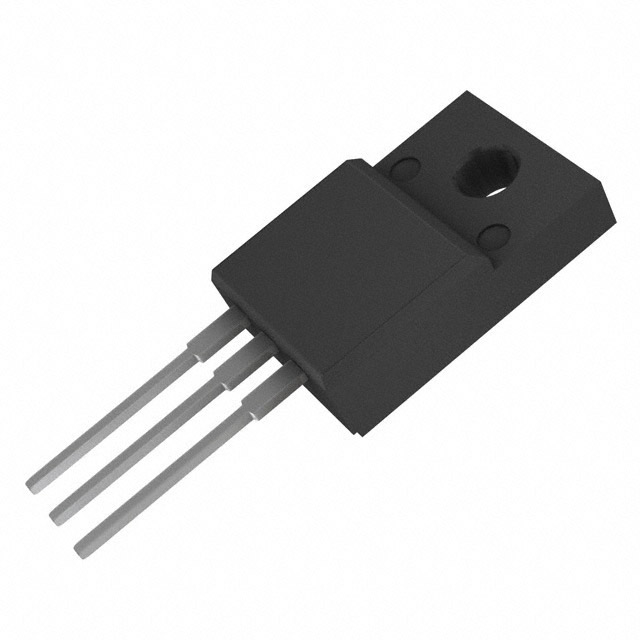
The IXFH13N80 is an N-Channel metal oxide semiconductor field-effect transistor (MOSFET) manufactured by IXYS, rated for 800V drain-to-source voltage and 13A continuous drain current at 25°C. The device is packaged in a TO-247AD through-hole configuration and is part of the HiPerFET™ series. This part carries a Last Time Buy product status, indicating that the manufacturer has discontinued active production. Identification of equivalent and substitute parts is necessary to ensure design continuity and maintain supply chain reliability for applications currently utilizing this component.
Substiute Parts
Key Parameters
| Parameter | Value | Unit |
|---|---|---|
| Drain-to-Source Voltage (Vdss) | 800 | V |
| Continuous Drain Current (Id) @ 25°C | 13 | A |
| On-State Resistance (Rds On Max) @ 500mA, 10V | 800 | mOhm |
| Gate Threshold Voltage (Vgs(th) Max) @ 4mA | 4.5 | V |
| Gate Charge (Qg Max) @ 10V | 155 | nC |
| Input Capacitance (Ciss Max) @ 25V | 4200 | pF |
| Power Dissipation (Max) | 300 | W |
| Operating Temperature Range | -55 to 150 | °C |
| Package Type | TO-247-3 | — |
| Mounting Type | Through Hole | — |
Substitute Part Grouping Explanation
Substitution of the IXFH13N80 is determined by the following critical electrical and mechanical parameters:
Primary Substitution Criteria:
- Drain-to-Source Voltage (Vdss): Must equal or exceed 800V
- Continuous Drain Current (Id): Must equal or exceed 13A at 25°C
- Gate Drive Voltage: Must support 10V drive operation
- Operating Temperature Range: Must span -55°C to 150°C
- Package Type: TO-247-3 or compatible through-hole configuration
- RoHS3 Compliance: Required for regulatory alignment
Secondary Compatibility Factors:
- On-State Resistance (Rds On): Lower values indicate improved performance
- Gate Charge (Qg): Lower values reduce switching losses
- Input Capacitance (Ciss): Affects gate drive requirements
- Power Dissipation Rating: Higher ratings provide thermal margin
Substitute parts are grouped into two categories: direct replacements with equivalent or superior electrical ratings, and functional alternatives that meet minimum application requirements while offering different performance trade-offs.
Parameter Comparison
| Parameter | IXFH13N80 | IXFH14N80P | IXFH14N85X | APT14M100B | FQAF13N80 | SPW11N80C3FKSA1 | SPW17N80C3FKSA1 | STW10NK80Z | STW12NK80Z |
|---|---|---|---|---|---|---|---|---|---|
| Manufacturer | IXYS | IXYS | IXYS | Microchip | onsemi | Infineon | Infineon | STMicroelectronics | STMicroelectronics |
| Vdss (V) | 800 | 800 | 850 | 1000 | 800 | 800 | 800 | 800 | 800 |
| Id @ 25°C (A) | 13 | 14 | 14 | 14 | 8 | 11 | 17 | 9 | 10.5 |
| Rds On Max @ 10V (mOhm) | 800 | 720 | 550 | 900 | 750 | 450 | 290 | 900 | 750 |
| Vgs(th) Max (V) | 4.5 | 5.5 | 5.5 | 5 | 5 | 3.9 | 3.9 | 4.5 | 4.5 |
| Qg Max @ 10V (nC) | 155 | 61 | 30 | 120 | 88 | 85 | 177 | 72 | 87 |
| Ciss Max @ 25V (pF) | 4200 | 3900 | 1043 | 3965 | 3500 | 1600 | 2320 | 2180 | 2620 |
| Power Dissipation Max (W) | 300 | 400 | 460 | 500 | 120 | 156 | 227 | 160 | 190 |
| Operating Temp Range (°C) | -55 to 150 | -55 to 150 | -55 to 150 | -55 to 150 | -55 to 150 | -55 to 150 | -55 to 150 | -55 to 150 | -55 to 150 |
| Package Type | TO-247-3 | TO-247-3 | TO-247-3 | TO-247-3 | TO-3P-3 | TO-247-3 | TO-247-3 | TO-247-3 | TO-247-3 |
| Product Status | Last Time Buy | Active | Active | Active | Obsolete | Not For New Designs | Active | Active | Active |
| RoHS3 Compliance | Yes | Yes | Yes | Yes | Yes | Yes | Yes | Yes | Yes |
Engineering Selection Recommendations
Tier 1 Direct Substitutes (Recommended for New Designs):
IXFH14N80P and SPW17N80C3FKSA1 are the primary recommended substitutes. Both parts maintain 800V Vdss rating, exceed the 13A minimum current requirement, and carry Active product status. IXFH14N80P provides a direct IXYS platform continuation with 14A rating and improved Rds On performance (720 mOhm vs. 800 mOhm). SPW17N80C3FKSA1 offers superior performance characteristics with 17A rating and significantly lower Rds On (290 mOhm), reducing conduction losses in high-frequency applications.
Tier 2 Functional Alternatives (Suitable for Existing Designs):
IXFH14N85X, APT14M100B, STW10NK80Z, and STW12NK80Z meet or exceed the electrical requirements of the IXFH13N80. IXFH14N85X provides higher voltage margin (850V) with improved Rds On (550 mOhm) and lower gate charge (30 nC). APT14M100B offers the highest voltage rating (1000V) for applications requiring additional voltage headroom. STW12NK80Z provides a balanced alternative with 10.5A rating and 750 mOhm Rds On, maintaining compatibility with existing thermal designs.
Not Recommended:
FQAF13N80 carries Obsolete product status and is not suitable for new designs or long-term supply continuity. SPW11N80C3FKSA1 carries Not For New Designs status and should be avoided for new applications.
All recommended substitutes maintain RoHS3 compliance, REACH unaffected status, and through-hole TO-247-3 packaging compatibility with the original IXFH13N80.
Frequently Asked Questions (FAQ)
Q: Can IXFH14N80P be used as a direct replacement for IXFH13N80?
A: Yes. IXFH14N80P meets all critical electrical parameters: 800V Vdss, 14A continuous drain current (exceeds 13A requirement), compatible 10V gate drive, and identical -55°C to 150°C operating range. Both devices use TO-247-3 packaging. IXFH14N80P is currently in Active production status, providing superior long-term supply availability compared to the Last Time Buy IXFH13N80.
Q: What is the difference between SPW17N80C3FKSA1 and IXFH14N80P?
A: Both parts meet the IXFH13N80 substitution requirements with 800V Vdss and current ratings exceeding 13A. SPW17N80C3FKSA1 offers superior performance with 17A rating, lower Rds On (290 mOhm vs. 720 mOhm), and significantly lower gate charge (177 nC vs. 61 nC). IXFH14N80P provides a closer electrical match to the original part. Selection depends on application requirements for switching speed and conduction loss optimization.
Q: Why is FQAF13N80 not recommended as a substitute?
A: FQAF13N80 carries Obsolete product status, indicating discontinued manufacturing and limited future availability. Additionally, the part uses TO-3PF packaging rather than TO-247-3, requiring PCB layout modifications. The 8A continuous drain current rating is below the 13A requirement of the IXFH13N80, making it unsuitable for equivalent performance.
Q: Are there package compatibility issues with any substitute parts?
A: All recommended substitutes use TO-247-3 through-hole packaging, maintaining mechanical and thermal interface compatibility with the IXFH13N80. FQAF13N80 uses TO-3P-3 Full Pack configuration and requires different mounting hardware and PCB layout, making it incompatible without design modification.
Q: What is the significance of Rds On differences between substitute parts?
A: On-state resistance (Rds On) directly affects conduction losses and thermal dissipation. Lower Rds On values reduce power loss during device operation. SPW17N80C3FKSA1 (290 mOhm) dissipates significantly less heat than IXFH13N80 (800 mOhm) at equivalent current levels. Selection should consider thermal design margins and application duty cycle requirements.
Q: Can APT14M100B be used in place of IXFH13N80?
A: Yes, with design considerations. APT14M100B exceeds all electrical requirements with 1000V Vdss (vs. 800V), 14A rating, and compatible operating temperature range. The higher voltage rating provides additional design margin for transient overvoltage conditions. However, the 900 mOhm Rds On is higher than the original part, resulting in increased conduction losses. This substitute is suitable for applications where voltage margin is prioritized over efficiency.
Q: What does "Not For New Designs" status mean for SPW11N80C3FKSA1?
A: This status indicates the manufacturer has discontinued active development and recommends against using this part in new circuit designs. While the part may remain available from inventory, long-term supply cannot be guaranteed. SPW11N80C3FKSA1 should only be considered for sustaining production of existing designs where supply from other alternatives is unavailable.
Q: How do gate charge differences affect circuit design?
A: Gate charge (Qg) determines the energy required to switch the MOSFET on and off. Lower gate charge reduces switching losses and allows faster switching speeds with lower gate drive power requirements. SPW17N80C3FKSA1 (177 nC) requires more gate charge than IXFH14N80P (61 nC), potentially requiring gate driver circuit adjustments in high-frequency applications. IXFH14N85X (30 nC) offers the lowest gate charge, enabling the fastest switching performance.
Alternative Parts

SJ6012L2TP
Littelfuse Inc.
6 Alternative Parts

JMK107BBJ476MA-RE
Taiyo Yuden
10 Alternative Parts

GMK107BBJ475MA-T
Taiyo Yuden
5 Alternative Parts
SJ6020N2ARP
Littelfuse Inc.
3 Alternative Parts
SJ6025R2ATP
Littelfuse Inc.
4 Alternative Parts

2474-05L
API Delevan Inc.
1 Alternative Parts

4590R-684K
API Delevan Inc.
1 Alternative Parts

CM6560R-334
API Delevan Inc.
1 Alternative Parts

CM6460-104
API Delevan Inc.
1 Alternative Parts

5526-12
API Delevan Inc.
1 Alternative Parts