


Request Quote
(Ships tomorrow)
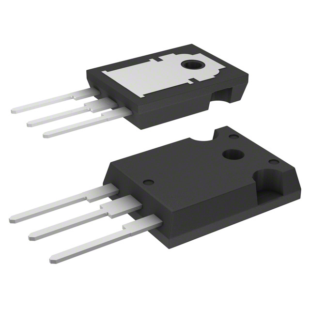
IXFH10N100Q N-Channel 1000V 10A MOSFET Equivalent & Substitute Parts
Part Overview
The IXFH10N100Q is an N-Channel MOSFET manufactured by IXYS, rated for 1000V drain-to-source voltage with 10A continuous drain current at 25°C. This device belongs to the HiPerFET™ Q Class series and is housed in a TO-247AD through-hole package. The part is Active in product status and RoHS3 compliant.
Substitute parts are identified when equivalent electrical performance can be achieved within the specified parameter ranges while maintaining compatible mechanical packaging and thermal characteristics. Alternative devices may be required due to inventory availability, supply chain considerations, or application-specific performance optimization within acceptable parameter tolerances.
Substiute Parts
Key Parameters
| Parameter | Value | Unit |
|---|---|---|
| Drain to Source Voltage (Vdss) | 1000 | V |
| Continuous Drain Current (Id) @ 25°C | 10 | A |
| Drive Voltage (Max Rds On) | 10 | V |
| Rds On (Max) @ Id, Vgs | 1.2 Ohm @ 5A, 10V | Ohm |
| Gate Threshold Voltage Vgs(th) (Max) @ Id | 4.5 | V @ 4mA |
| Gate Charge (Qg) (Max) @ Vgs | 155 | nC @ 10V |
| Power Dissipation (Max) | 300 | W |
| Operating Temperature Range | -55 to 150 | °C |
| Mounting Type | Through Hole | — |
| Package Type | TO-247-3 | — |
| FET Type | N-Channel | — |
| Technology | MOSFET (Metal Oxide) | — |
Substitute Part Grouping Explanation
Substitution eligibility for N-Channel MOSFETs is determined by the following critical parameters:
Voltage Rating Compatibility: The substitute device must support the application's maximum drain-to-source voltage requirement. The IXFH10N100Q operates at 1000V Vdss. Substitute parts with equal or higher Vdss ratings are electrically compatible for voltage stress conditions.
Current Handling Capacity: The continuous drain current (Id) at 25°C must meet or exceed the application's current demand. The IXFH10N100Q is rated for 10A continuous drain current. Substitute devices with Id ratings of 9A or higher maintain functional equivalence for current-carrying applications.
On-State Resistance (Rds On): This parameter directly affects power dissipation and thermal performance. The IXFH10N100Q specifies 1.2 Ohm maximum at 5A, 10V gate-source voltage. Substitute parts with comparable or lower Rds On values ensure equivalent or improved efficiency characteristics.
Gate Charge (Qg): This parameter influences switching speed and gate drive requirements. The IXFH10N100Q specifies 155 nC maximum at 10V. Lower gate charge values indicate faster switching performance.
Power Dissipation Rating: The IXFH10N100Q is rated for 300W maximum power dissipation. Substitute devices must support the thermal requirements of the target application.
Package and Mounting: All substitute parts must use compatible through-hole TO-247-3 packaging to ensure mechanical and thermal interface compatibility.
Operating Temperature Range: All candidates maintain the -55°C to 150°C operating temperature range, ensuring thermal compatibility across industrial and commercial applications.
Parameter Comparison
| Parameter | IXFH10N100Q | STW11NK90Z | STW6N95K5 | Unit |
|---|---|---|---|---|
| Manufacturer | IXYS | STMicroelectronics | STMicroelectronics | — |
| Drain to Source Voltage (Vdss) | 1000 | 900 | 950 | V |
| Continuous Drain Current (Id) @ 25°C | 10 | 9.2 | 9 | A |
| Drive Voltage (Max Rds On) | 10 | 10 | 10 | V |
| Rds On (Max) @ Id, Vgs | 1.2 @ 5A, 10V | 0.98 @ 4.6A, 10V | 1.25 @ 3A, 10V | Ohm |
| Gate Threshold Voltage Vgs(th) (Max) @ Id | 4.5 @ 4mA | 4.5 @ 100µA | 5 @ 100µA | V |
| Gate Charge (Qg) (Max) @ Vgs | 155 @ 10V | 115 @ 10V | 13 @ 10V | nC |
| Vgs (Max) | ±20 | ±30 | ±30 | V |
| Input Capacitance (Ciss) (Max) @ Vds | 4000 @ 25V | 3000 @ 25V | 450 @ 100V | pF |
| Power Dissipation (Max) | 300 | 200 | 90 | W |
| Operating Temperature Range | -55 to 150 | -55 to 150 | -55 to 150 | °C |
| Mounting Type | Through Hole | Through Hole | Through Hole | — |
| Package Type | TO-247-3 | TO-247-3 | TO-247-3 | — |
| FET Type | N-Channel | N-Channel | N-Channel | — |
| Technology | MOSFET (Metal Oxide) | MOSFET (Metal Oxide) | MOSFET (Metal Oxide) | — |
| RoHS Status | ROHS3 Compliant | ROHS3 Compliant | ROHS3 Compliant | — |
| Product Status | Active | Active | Active | — |
Engineering Selection Recommendations
IXFH10N100Q (Primary Part)
The IXFH10N100Q remains the primary selection for applications requiring the full 1000V voltage rating and 10A continuous current capacity. This device delivers 300W maximum power dissipation and is manufactured by IXYS within the HiPerFET™ Q Class series. The part is Active in product status with RoHS3 compliance and REACH unaffected status, confirming regulatory alignment for industrial and commercial deployment.
STW11NK90Z (Substitute Option)
The STW11NK90Z from STMicroelectronics operates at 900V Vdss with 9.2A continuous drain current, representing a 100V voltage derating and 0.8A current reduction relative to the primary part. This device exhibits lower on-state resistance (0.98 Ohm at 4.6A, 10V) and reduced gate charge (115 nC), resulting in improved switching efficiency. Power dissipation is rated at 200W. The STW11NK90Z is suitable for applications where the 900V voltage rating is sufficient and where reduced switching losses provide system-level benefits. Active product status and RoHS3 compliance confirm production availability and regulatory compliance.
STW6N95K5 (Substitute Option)
The STW6N95K5 from STMicroelectronics operates at 950V Vdss with 9A continuous drain current, representing a 50V voltage derating and 1A current reduction. This device exhibits significantly reduced gate charge (13 nC) and input capacitance (450 pF at 100V), indicating substantially faster switching characteristics. Power dissipation is rated at 90W. The STW6N95K5 is suitable for applications where the 950V voltage rating is acceptable and where minimal gate charge and capacitance are critical for high-frequency switching performance. Active product status and RoHS3 compliance confirm production availability and regulatory compliance.
Frequently Asked Questions (FAQ)
Q: Can the STW11NK90Z be used in place of the IXFH10N100Q in all applications?
A: The STW11NK90Z operates at 900V Vdss compared to the IXFH10N100Q's 1000V rating. Substitution is valid only for applications where the maximum voltage stress does not exceed 900V. The 9.2A continuous current rating is slightly lower than the 10A specification of the primary part. Verify that application current requirements do not exceed 9.2A at 25°C.
Q: What are the switching performance differences between these devices?
A: Gate charge (Qg) directly influences switching speed and gate drive power requirements. The IXFH10N100Q specifies 155 nC, the STW11NK90Z specifies 115 nC, and the STW6N95K5 specifies 13 nC. Lower gate charge enables faster switching transitions and reduced gate drive losses. Input capacitance (Ciss) also affects switching behavior; the STW6N95K5 exhibits significantly lower capacitance (450 pF at 100V) compared to the IXFH10N100Q (4000 pF at 25V).
Q: Are all substitute parts compatible with the same PCB layout and thermal interface?
A: All three devices use TO-247-3 through-hole packaging with identical mechanical dimensions and pin configurations. PCB layouts and thermal interface designs (heatsink mounting) are directly compatible. Verify that thermal management provisions accommodate the power dissipation rating of the selected device; the STW6N95K5 is rated for 90W compared to the IXFH10N100Q's 300W.
Q: What is the impact of on-state resistance (Rds On) differences?
A: On-state resistance directly determines conduction losses and heat generation. The IXFH10N100Q specifies 1.2 Ohm at 5A, 10V. The STW11NK90Z specifies 0.98 Ohm at 4.6A, 10V, and the STW6N95K5 specifies 1.25 Ohm at 3A, 10V. Lower Rds On values reduce I²R losses during conduction. Comparison must account for the different measurement conditions (current and gate voltage) specified by each manufacturer.
Q: Are gate threshold voltage differences significant for circuit design?
A: Gate threshold voltage (Vgs(th)) determines the minimum gate-source voltage required to turn the device on. The IXFH10N100Q specifies 4.5V at 4mA, the STW11NK90Z specifies 4.5V at 100µA, and the STW6N95K5 specifies 5V at 100µA. These differences are minor and do not typically require gate drive circuit modifications for standard 10V or 15V gate drive supplies.
Q: What compliance certifications apply to all substitute parts?
A: All three devices are RoHS3 compliant, REACH unaffected, and classified under ECCN EAR99. All devices maintain Active product status, confirming ongoing manufacturing support and availability. Moisture sensitivity level is 1 (Unlimited) for all parts, indicating no special moisture control requirements during storage or handling.
Q: How should power dissipation ratings influence device selection?
A: Power dissipation ratings reflect the maximum thermal load the device can sustain under specified conditions. The IXFH10N100Q is rated for 300W, the STW11NK90Z for 200W, and the STW6N95K5 for 90W. Applications with high continuous current or high switching frequency may generate power dissipation approaching these limits. Thermal management design must accommodate the selected device's power rating to maintain junction temperature within the -55°C to 150°C operating range.
Alternative Parts

SJ6012L2TP
Littelfuse Inc.
6 Alternative Parts

JMK107BBJ476MA-RE
Taiyo Yuden
10 Alternative Parts

GMK107BBJ475MA-T
Taiyo Yuden
5 Alternative Parts
SJ6020N2ARP
Littelfuse Inc.
3 Alternative Parts
SJ6025R2ATP
Littelfuse Inc.
4 Alternative Parts

2474-05L
API Delevan Inc.
1 Alternative Parts

4590R-684K
API Delevan Inc.
1 Alternative Parts

CM6560R-334
API Delevan Inc.
1 Alternative Parts

CM6460-104
API Delevan Inc.
1 Alternative Parts

5526-12
API Delevan Inc.
1 Alternative Parts