


Request Quote
(Ships tomorrow)
IXFA4N100Q N-Channel 1000V 4A MOSFET Equivalent & Substitute Parts
Part Overview
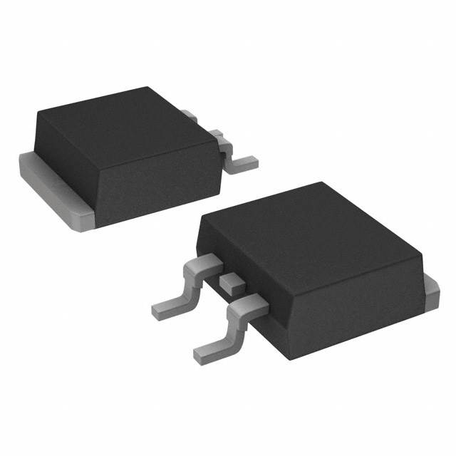
The IXFA4N100Q is an N-Channel MOSFET manufactured by IXYS, rated for 1000V drain-to-source voltage with 4A continuous drain current at 25°C. This device belongs to the HiPerFET™ Q Class series and is designed for high-voltage switching applications requiring surface mount integration in TO-263AA packaging. The part is currently active in production with 3254 units in stock.
Substitute parts are identified when equivalent electrical performance can be achieved within the specified parameter tolerances while maintaining compatibility with the TO-263 package family and surface mount assembly requirements.
Substiute Parts
Key Parameters
| Parameter | Value | Unit |
|---|---|---|
| Drain-to-Source Voltage (Vdss) | 1000 | V |
| Continuous Drain Current (Id) @ 25°C | 4 | A |
| On-State Resistance (Rds On) @ 2A, 10V | 3 | Ω |
| Gate Threshold Voltage (Vgs(th)) @ 1.5mA | 4.5 | V |
| Power Dissipation (Max) | 150 | W |
| Operating Temperature Range | -55 to 150 | °C |
| Package Type | TO-263-3 (D2PAK) | — |
| Mounting Type | Surface Mount | — |
Substitute Part Grouping Explanation
Substitution eligibility for the IXFA4N100Q is determined by the following critical parameters:
Voltage Rating Compatibility: The substitute part must support the application's maximum operating voltage. The IXFA4N100Q operates at 1000V Vdss. Substitute parts with lower voltage ratings (such as 900V) may be considered only when the application circuit design ensures the actual operating voltage remains within the substitute's rated specification.
Current Handling Capacity: The substitute must support continuous drain current requirements. The IXFA4N100Q is rated for 4A continuous drain current. Substitute parts with lower current ratings require verification that peak and average current demands do not exceed the substitute's specification.
On-State Resistance (Rds On): This parameter directly affects power dissipation and thermal performance. The IXFA4N100Q specifies 3Ω maximum at 2A and 10V gate drive. Substitute parts with higher Rds On values will generate increased heat and may require thermal management adjustments.
Package Compatibility: Both the main part and substitute must use the TO-263 package family (D2PAK configuration with 2 leads plus tab) to ensure mechanical and thermal compatibility with existing PCB layouts and assembly processes.
Temperature Range: The operating temperature range of -55°C to 150°C must be supported by the substitute part to maintain reliability across the intended application environment.
Parameter Comparison
| Parameter | IXFA4N100Q | IRFBF30STRLPBF | Unit |
|---|---|---|---|
| Manufacturer | IXYS | Vishay Siliconix | — |
| FET Type | N-Channel | N-Channel | — |
| Drain-to-Source Voltage (Vdss) | 1000 | 900 | V |
| Continuous Drain Current (Id) @ 25°C | 4 | 3.6 | A |
| On-State Resistance (Rds On) @ 10V | 3 @ 2A | 3.7 @ 2.2A | Ω |
| Gate Threshold Voltage (Vgs(th)) | 4.5 @ 1.5mA | 4 @ 250µA | V |
| Gate Charge (Qg) @ 10V | 39 | 78 | nC |
| Input Capacitance (Ciss) @ 25V | 1050 | 1200 | pF |
| Power Dissipation (Max) | 150 | 125 | W |
| Operating Temperature Range | -55 to 150 | -55 to 150 | °C |
| Package Type | TO-263-3 (D2PAK) | TO-263-3 (D2PAK) | — |
| Mounting Type | Surface Mount | Surface Mount | — |
| RoHS Status | ROHS3 Compliant | ROHS3 Compliant | — |
| Moisture Sensitivity Level (MSL) | 1 (Unlimited) | 1 (Unlimited) | — |
| Product Status | Active | Active | — |
Engineering Selection Recommendations
IRFBF30STRLPBF as Substitute for IXFA4N100Q:
The IRFBF30STRLPBF is an active production part manufactured by Vishay Siliconix with full RoHS3 compliance and MSL Level 1 rating, matching the compliance profile of the IXFA4N100Q.
Compatibility Considerations:
The IRFBF30STRLPBF operates at 900V Vdss compared to the IXFA4N100Q's 1000V rating. This 100V difference represents a 10% reduction in voltage headroom. Selection of this substitute is appropriate only when the application circuit design ensures that maximum operating voltage remains below 900V under all conditions, including transient overvoltage events.
The continuous drain current rating of 3.6A on the IRFBF30STRLPBF is 10% lower than the IXFA4N100Q's 4A specification. Applications requiring sustained current near 4A may experience thermal stress with this substitute.
The on-state resistance of 3.7Ω at 2.2A and 10V is marginally higher than the IXFA4N100Q's 3Ω at 2A and 10V. This results in approximately 23% higher power dissipation at equivalent current levels. The maximum power dissipation rating of 125W is also 17% lower than the IXFA4N100Q's 150W specification.
Gate charge (Qg) on the IRFBF30STRLPBF is 78nC at 10V, approximately double the IXFA4N100Q's 39nC. This increased gate charge will require higher gate drive current or longer switching times, affecting circuit performance in high-frequency applications.
Both parts share identical operating temperature range (-55°C to 150°C), package type (TO-263-3 D2PAK), and mounting configuration (surface mount), ensuring mechanical and thermal compatibility with existing PCB designs.
Frequently Asked Questions (FAQ)
Q: Can the IRFBF30STRLPBF directly replace the IXFA4N100Q in all applications?
A: No. The IRFBF30STRLPBF has lower voltage (900V vs. 1000V), current (3.6A vs. 4A), and power dissipation (125W vs. 150W) ratings. Substitution is valid only when the application circuit operates within these lower specifications and does not require the full performance envelope of the IXFA4N100Q.
Q: What is the impact of the higher gate charge on the IRFBF30STRLPBF?
A: The IRFBF30STRLPBF requires approximately twice the gate charge (78nC vs. 39nC) compared to the IXFA4N100Q. This increases gate drive circuit demands and may extend switching times, affecting efficiency in high-frequency switching applications.
Q: Are both parts compatible with the same PCB layout?
A: Yes. Both the IXFA4N100Q and IRFBF30STRLPBF use the TO-263-3 (D2PAK) package with identical pin configuration and thermal tab placement, allowing direct PCB layout compatibility without modification.
Q: What compliance certifications apply to both parts?
A: Both parts are RoHS3 compliant and carry MSL Level 1 (unlimited moisture sensitivity level) ratings. Both are active production parts with no known end-of-life status.
Q: How does the higher on-state resistance of the IRFBF30STRLPBF affect thermal design?
A: The IRFBF30STRLPBF's 3.7Ω on-state resistance generates approximately 23% more heat than the IXFA4N100Q's 3Ω at equivalent current levels. Combined with its lower maximum power dissipation rating (125W vs. 150W), thermal management may require enhanced heatsinking or reduced operating current.
Q: Can the IRFBF30STRLPBF be used in 1000V applications?
A: No. The IRFBF30STRLPBF is rated for maximum 900V Vdss. Using this part in circuits designed for 1000V operation creates risk of device failure and potential circuit damage.
Alternative Parts

SJ6012L2TP
Littelfuse Inc.
6 Alternative Parts

JMK107BBJ476MA-RE
Taiyo Yuden
10 Alternative Parts

GMK107BBJ475MA-T
Taiyo Yuden
5 Alternative Parts
SJ6020N2ARP
Littelfuse Inc.
3 Alternative Parts
SJ6025R2ATP
Littelfuse Inc.
4 Alternative Parts

2474-05L
API Delevan Inc.
1 Alternative Parts

4590R-684K
API Delevan Inc.
1 Alternative Parts

CM6560R-334
API Delevan Inc.
1 Alternative Parts

CM6460-104
API Delevan Inc.
1 Alternative Parts

5526-12
API Delevan Inc.
1 Alternative Parts