


Request Quote
(Ships tomorrow)
IX2113G Equivalent & Substitute Parts
Part Overview
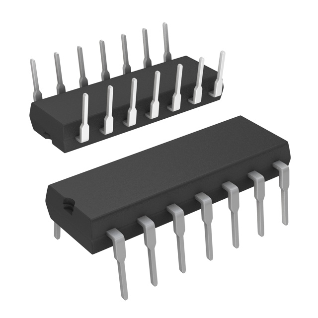
The IX2113G is a half-bridge gate driver IC manufactured by IXYS Integrated Circuits Division, designed for driving IGBT and MOSFET devices in power management applications. This device features independent dual-channel configuration with non-inverting inputs and is packaged in a 14-DIP through-hole format. The IX2113G is classified as obsolete, making identification of functionally equivalent substitute components essential for ongoing system support and new design implementations.
Substiute Parts
Key Parameters
| Parameter | IX2113G Specification |
|---|---|
| Driven Configuration | Half-Bridge |
| Number of Drivers | 2 |
| Gate Type | IGBT, N-Channel, P-Channel MOSFET |
| Voltage - Supply | 10V ~ 20V |
| Logic Voltage - VIL, VIH | 6V, 9.5V |
| Current - Peak Output (Source, Sink) | 2A, 2A |
| Input Type | Non-Inverting |
| High Side Voltage - Max (Bootstrap) | 600V |
| Operating Temperature | -40°C ~ 150°C (TJ) |
| Mounting Type | Through Hole |
| Package / Case | 14-DIP (0.300", 7.62mm) |
| RoHS Status | ROHS3 Compliant |
Substitute Part Grouping Explanation
Substitution of the IX2113G requires functional equivalence across core electrical parameters that define gate driver operation: supply voltage range, logic signal levels, output current capability, and bootstrap voltage rating. The FAN73912MX qualifies as a substitute based on the following alignment criteria:
Matching Parameters:
- Dual-channel driver configuration (2 drivers)
- Non-inverting input type
- Supply voltage range overlap (12V ~ 20V encompasses the upper operating range of IX2113G)
- Logic voltage thresholds (VIL 6V, VIH 9.5V) identical to original
- Peak output current capability (2A source minimum, meeting or exceeding IX2113G requirements)
- ROHS3 compliance and EAR99 classification
Functional Differences:
- FAN73912MX supports high-side and low-side configuration versus half-bridge only
- Bootstrap voltage rating increased to 1200V (higher capability)
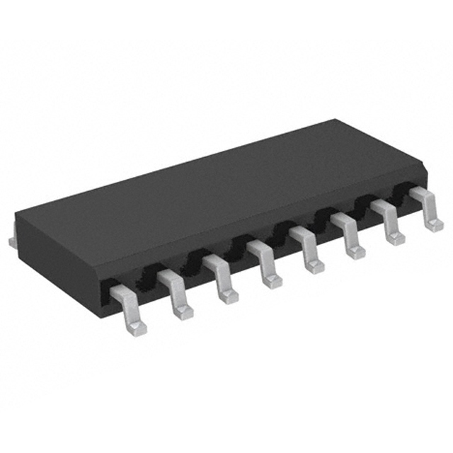
- Surface mount packaging (16-SOIC) versus through-hole (14-DIP)
- Operating temperature range reduced to -40°C ~ 125°C
Parameter Comparison
| Parameter | IX2113G | FAN73912MX | Compatibility Notes |
|---|---|---|---|
| Number of Drivers | 2 | 2 | Equivalent |
| Voltage - Supply | 10V ~ 20V | 12V ~ 20V | Overlapping range; FAN73912MX requires minimum 12V |
| Logic Voltage - VIL, VIH | 6V, 9.5V | 6V, 9.5V | Identical |
| Current - Peak Output (Source, Sink) | 2A, 2A | 2A, 3A | FAN73912MX meets or exceeds requirements |
| Input Type | Non-Inverting | Non-Inverting | Equivalent |
| High Side Voltage - Max (Bootstrap) | 600V | 1200V | FAN73912MX provides higher rating |
| Operating Temperature | -40°C ~ 150°C | -40°C ~ 125°C | FAN73912MX has reduced upper limit |
| Mounting Type | Through Hole | Surface Mount | Different assembly method required |
| Package / Case | 14-DIP | 16-SOIC | PCB layout redesign necessary |
| RoHS Status | ROHS3 Compliant | ROHS3 Compliant | Equivalent |
Engineering Selection Recommendations
The FAN73912MX serves as a functional substitute for the obsolete IX2113G in applications where the following conditions are met:
-
Supply Voltage Constraint: System supply voltage must operate at or above 12V. Applications limited to the 10V ~ 12V range of the IX2113G cannot use FAN73912MX without supply modification.
-
Temperature Constraint: Maximum junction temperature requirement must not exceed 125°C. Applications requiring operation above 125°C require alternative solutions.
-
Packaging Accommodation: PCB redesign is mandatory due to transition from 14-DIP through-hole to 16-SOIC surface mount. Pin-to-pin compatibility does not exist.
-
Compliance Status: Both devices maintain ROHS3 compliance and EAR99 classification, ensuring regulatory equivalence for procurement and deployment.
The FAN73912MX is classified as active product status, providing long-term availability and supply chain stability compared to the obsolete IX2113G.
Frequently Asked Questions (FAQ)
Q: Can the FAN73912MX be used as a direct pin-for-pin replacement for the IX2113G?
A: No. The IX2113G uses 14-DIP through-hole packaging while the FAN73912MX uses 16-SOIC surface mount packaging. Pin assignments differ, requiring complete PCB redesign and layout modification.
Q: What is the minimum supply voltage for the FAN73912MX?
A: The FAN73912MX requires a minimum supply voltage of 12V. The IX2113G operates from 10V minimum. Applications with supply voltages between 10V and 12V cannot use the FAN73912MX without supply circuit modification.
Q: Are the logic input voltage thresholds identical between these devices?
A: Yes. Both the IX2113G and FAN73912MX specify VIL of 6V and VIH of 9.5V, ensuring compatible signal conditioning and control circuitry.
Q: Does the FAN73912MX provide sufficient output current for IX2113G applications?
A: Yes. The FAN73912MX provides 2A source current and 3A sink current, meeting or exceeding the 2A source and 2A sink specification of the IX2113G.
Q: What is the impact of the reduced operating temperature range in the FAN73912MX?
A: The FAN73912MX maximum junction temperature is 125°C versus 150°C for the IX2113G. Applications requiring sustained operation above 125°C must use alternative gate driver solutions.
Q: Are both devices RoHS compliant?
A: Yes. Both the IX2113G and FAN73912MX are ROHS3 compliant, meeting environmental and regulatory requirements for component procurement and system deployment.
Alternative Parts

SJ6012L2TP
Littelfuse Inc.
6 Alternative Parts

JMK107BBJ476MA-RE
Taiyo Yuden
10 Alternative Parts

GMK107BBJ475MA-T
Taiyo Yuden
5 Alternative Parts
SJ6020N2ARP
Littelfuse Inc.
3 Alternative Parts
SJ6025R2ATP
Littelfuse Inc.
4 Alternative Parts

2474-05L
API Delevan Inc.
1 Alternative Parts

4590R-684K
API Delevan Inc.
1 Alternative Parts

CM6560R-334
API Delevan Inc.
1 Alternative Parts

CM6460-104
API Delevan Inc.
1 Alternative Parts

5526-12
API Delevan Inc.
1 Alternative Parts