


Request Quote
(Ships tomorrow)
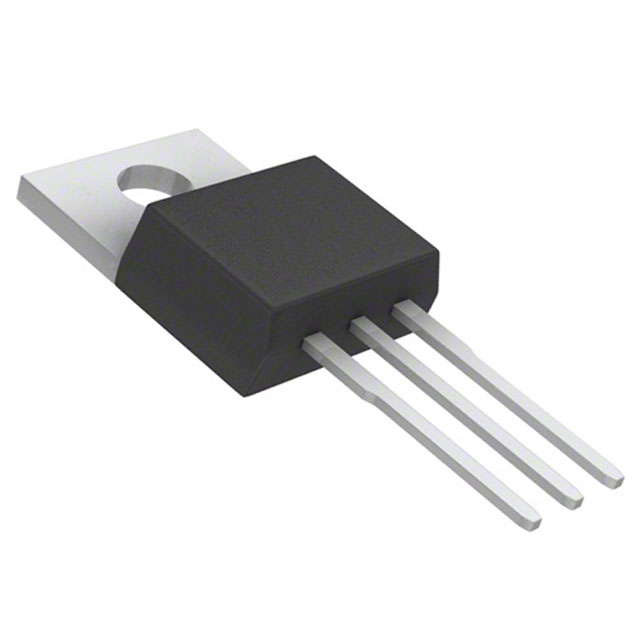
IRLZ44ZPBF N-Channel 55V 51A MOSFET Equivalent & Substitute Parts
Part Overview
The IRLZ44ZPBF is an N-Channel MOSFET manufactured by Infineon Technologies, rated for 55V drain-to-source voltage and 51A continuous drain current in a TO-220AB through-hole package. This device is classified as obsolete, making equivalent and substitute parts necessary for ongoing design support and procurement continuity. The HEXFET® series device operates across a temperature range of -55°C to 175°C and dissipates up to 80W at the case temperature. Substitution requires matching or exceeding the electrical performance envelope while maintaining mechanical compatibility with the TO-220 form factor.
Substiute Parts
Key Parameters
| Parameter | Value | Unit |
|---|---|---|
| Drain-to-Source Voltage (Vdss) | 55 | V |
| Continuous Drain Current (Id) @ 25°C | 51 | A |
| On-State Resistance (Rds On) @ 31A, 10V | 13.5 | mOhm |
| Gate Threshold Voltage (Vgs(th)) @ 250µA | 3 | V |
| Gate Charge (Qg) @ 5V | 36 | nC |
| Power Dissipation (Max) | 80 | W |
| Operating Temperature Range | -55 to 175 | °C |
| Package Type | TO-220AB | — |
| Mounting Type | Through Hole | — |
Substitute Part Grouping Explanation
Substitution of the IRLZ44ZPBF is determined by the following critical electrical and mechanical parameters:
Primary Matching Criteria:
- Drain-to-Source Voltage (Vdss): Must equal or exceed 55V
- Continuous Drain Current (Id): Must equal or exceed 51A at 25°C
- Package Type: TO-220 form factor (TO-220AB or TO-220-3 compatible)
- Mounting Type: Through-hole configuration
- Operating Temperature Range: Must span -55°C to 175°C minimum
Secondary Performance Considerations:
- On-State Resistance (Rds On): Lower values indicate improved efficiency
- Gate Charge (Qg): Affects switching speed and drive circuit requirements
- Power Dissipation Rating: Higher ratings provide thermal margin
- Gate Threshold Voltage (Vgs(th)): Determines gate drive compatibility
The substitute parts listed below meet or exceed the primary matching criteria. Variations in secondary parameters reflect different design optimizations within the N-Channel MOSFET category and do not preclude functional substitution.
Parameter Comparison
| Part Number | Manufacturer | Vdss (V) | Id @ 25°C (A) | Rds On (mOhm) | Vgs(th) (V) | Qg (nC) | Power Diss. (W) | Package | Status |
|---|---|---|---|---|---|---|---|---|---|
| IRLZ44ZPBF | Infineon | 55 | 51 | 13.5 | 3 | 36 | 80 | TO-220AB | Obsolete |
| HUF75332P3 | onsemi | 55 | 60 | 19 | 4 | 85 | 145 | TO-220-3 | Active |
| HUF75339P3 | onsemi | 55 | 75 | 12 | 4 | 130 | 200 | TO-220-3 | Active |
| HUF75344P3 | onsemi | 55 | 75 | 8 | 4 | 210 | 285 | TO-220-3 | Active |
| IRLZ44PBF | Vishay Siliconix | 60 | 50 | 28 | 2 | 66 | 150 | TO-220AB | Active |
| IXTP70N075T2 | IXYS | 75 | 70 | 12 | 4 | 46 | 150 | TO-220-3 | Active |
| PHP191NQ06LT,127 | Nexperia USA Inc. | 55 | 75 | 3.7 | 2 | 95.6 | 300 | TO-220AB | Obsolete |
| STP55NF06L | STMicroelectronics | 60 | 55 | 18 | 1.7 | 37 | 95 | TO-220 | Active |
| STP60NF06L | STMicroelectronics | 60 | 60 | 14 | 1 | 66 | 110 | TO-220 | Active |
Engineering Selection Recommendations
For Active Product Continuity:
The following active-status parts provide direct functional substitution with enhanced performance characteristics:
HUF75344P3 (onsemi UltraFET™): Matches 55V Vdss rating with 75A continuous current capability, superior on-state resistance of 8mOhm, and 285W power dissipation. TO-220-3 package maintains mechanical compatibility. ROHS3 compliant. Recommended for applications requiring improved thermal performance and lower conduction losses.
STP60NF06L (STMicroelectronics STripFET™ II): Provides 60V Vdss with 60A continuous current, 14mOhm on-state resistance, and 110W power dissipation. TO-220 package compatible. ROHS3 compliant. Suitable for general-purpose switching applications with moderate thermal requirements.
IRLZ44PBF (Vishay Siliconix): Maintains TO-220AB package compatibility with 60V Vdss and 50A continuous current. Higher on-state resistance (28mOhm) and lower power dissipation (150W) reflect different design optimization. ROHS3 compliant. REACH affected status requires verification for regulated markets.
For Higher Current or Thermal Margin Applications:
HUF75339P3 (onsemi UltraFET™): 55V Vdss, 75A continuous current, 12mOhm on-state resistance, 200W power dissipation. TO-220-3 package. ROHS3 compliant. Provides significant current and thermal headroom.
IXTP70N075T2 (IXYS TrenchT2™): 75V Vdss, 70A continuous current, 12mOhm on-state resistance, 150W power dissipation. TO-220-3 package. ROHS3 compliant. Suitable for applications requiring higher voltage margin.
For Obsolete Product Replacement with Maximum Performance:
PHP191NQ06LT,127 (Nexperia TrenchMOS™): Matches 55V Vdss with 75A continuous current and exceptional 3.7mOhm on-state resistance. 300W power dissipation provides maximum thermal capability. TO-220AB package maintains mechanical compatibility. ROHS3 compliant. Note: Product status is obsolete; verify long-term availability.
All recommended substitutes maintain the -55°C to 175°C operating temperature range and are ROHS3 compliant. Package mechanical compatibility with TO-220 form factor is confirmed for all listed parts.
Frequently Asked Questions (FAQ)
Q: Can I use HUF75332P3 as a direct replacement for IRLZ44ZPBF?
A: HUF75332P3 meets the primary substitution criteria: 55V Vdss, 60A continuous current (exceeds 51A requirement), and TO-220-3 package compatibility. The higher on-state resistance (19mOhm vs. 13.5mOhm) results in increased conduction losses. Thermal design verification is required if the original design operated near the 80W dissipation limit.
Q: What is the difference between TO-220AB and TO-220-3 packages?
A: Both are through-hole TO-220 form factors with identical pin pitch and mounting hole spacing. TO-220AB and TO-220-3 designations reflect different manufacturer conventions but are mechanically and electrically interchangeable in standard PCB layouts. Verify specific lead configuration requirements for your application.
Q: Why does IRLZ44PBF have higher on-state resistance than IRLZ44ZPBF?
A: IRLZ44PBF is rated for 60V Vdss compared to IRLZ44ZPBF at 55V. Higher voltage rating typically results in higher on-state resistance due to increased die area required for voltage blocking capability. The 28mOhm vs. 13.5mOhm difference reflects this voltage-resistance tradeoff inherent to MOSFET design.
Q: Are all substitute parts ROHS3 compliant?
A: Yes. All listed substitute parts carry ROHS3 compliance certification. IRLZ44PBF carries REACH affected status; verify regulatory requirements for your end market before selection.
Q: Which substitute offers the lowest on-state resistance?
A: PHP191NQ06LT,127 provides 3.7mOhm on-state resistance, the lowest among all listed parts. This results in minimal conduction losses and reduced thermal generation. However, product status is obsolete; confirm availability with suppliers before design commitment.
Q: Can I use IXTP70N075T2 in a 55V application?
A: Yes. IXTP70N075T2 is rated for 75V Vdss, which exceeds the 55V requirement. The higher voltage rating provides design margin but does not prevent operation at 55V. Verify gate drive voltage compatibility: IXTP70N075T2 requires 10V gate drive, while IRLZ44ZPBF operates at 4.5V to 10V.
Q: What is the impact of higher gate charge on circuit design?
A: Gate charge (Qg) determines the total charge required to switch the MOSFET on or off. Higher gate charge (e.g., HUF75344P3 at 210nC vs. IRLZ44ZPBF at 36nC) requires higher gate drive current or longer switching times. Verify gate driver capability before substitution if switching frequency is critical.
Q: Is mechanical pin compatibility guaranteed across all TO-220 variants?
A: Yes. All TO-220AB and TO-220-3 packages share identical pin pitch (2.54mm), mounting hole spacing, and lead configuration. Standard PCB footprints accommodate all listed parts without modification.
Alternative Parts

SJ6012L2TP
Littelfuse Inc.
6 Alternative Parts

JMK107BBJ476MA-RE
Taiyo Yuden
10 Alternative Parts

GMK107BBJ475MA-T
Taiyo Yuden
5 Alternative Parts
SJ6020N2ARP
Littelfuse Inc.
3 Alternative Parts
SJ6025R2ATP
Littelfuse Inc.
4 Alternative Parts

2474-05L
API Delevan Inc.
1 Alternative Parts

4590R-684K
API Delevan Inc.
1 Alternative Parts

CM6560R-334
API Delevan Inc.
1 Alternative Parts

CM6460-104
API Delevan Inc.
1 Alternative Parts

5526-12
API Delevan Inc.
1 Alternative Parts