


Request Quote
(Ships tomorrow)
IRLU7833 N-Channel MOSFET 30V 140A Equivalent & Substitute Parts
Part Overview
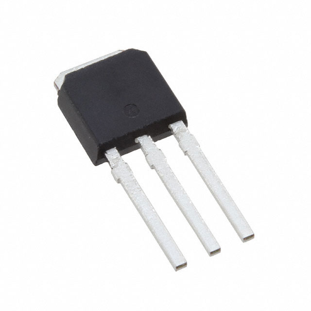
The IRLU7833 is an N-Channel MOSFET manufactured by Infineon Technologies, designed for high-current switching applications with a 30V drain-to-source voltage rating and 140A continuous drain current capability. This device features the HEXFET® series technology in a Through Hole IPAK (TO-251AA) package configuration.
The IRLU7833 is classified as Obsolete, indicating it is no longer in active production. Locating equivalent or substitute components becomes necessary for ongoing maintenance, repair, and legacy system support where original parts are no longer readily available through standard distribution channels.
Substiute Parts
Key Parameters
| Parameter | Value | Unit |
|---|---|---|
| Drain to Source Voltage (Vdss) | 30 | V |
| Continuous Drain Current (Id) @ 25°C | 140 | A |
| Rds On (Max) @ 15A, 10V | 4.5 | mOhm |
| Gate Threshold Voltage (Vgs(th)) @ 250µA | 2.3 | V |
| Gate Charge (Qg) @ 4.5V | 50 | nC |
| Power Dissipation (Max) | 140 | W |
| Operating Temperature Range | -55 to 175 | °C |
| Package Type | TO-251-3 Short Leads, IPAK | — |
| Mounting Type | Through Hole | — |
Substitute Part Grouping Explanation
Substitution of the IRLU7833 is evaluated based on electrical and mechanical compatibility within the N-Channel MOSFET category. The critical parameters determining substitutability are:
Electrical Compatibility Criteria:
- Drain-to-Source Voltage (Vdss) must be equal to or greater than 30V
- Continuous Drain Current (Id) must meet or exceed 140A at 25°C
- Gate threshold voltage (Vgs(th)) must fall within acceptable switching margins
- On-state resistance (Rds On) characteristics must support the intended application current levels
- Gate charge (Qg) must be compatible with existing gate drive circuitry
- Maximum gate voltage (Vgs Max) must be ±20V or greater
Mechanical Compatibility Criteria:
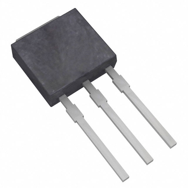
- Package type must be TO-251-3 Short Leads / IPAK (TO-251AA)
- Mounting configuration must be Through Hole
- Pin configuration must match the three-terminal FET standard (Gate, Drain, Source)
The IRLU8743PBF qualifies as a direct substitute based on these parameters, as it maintains identical voltage ratings, exceeds current capability, and shares the same package and mounting specifications.
Parameter Comparison
| Parameter | IRLU7833 | IRLU8743PBF | Compatibility |
|---|---|---|---|
| Drain to Source Voltage (Vdss) | 30 V | 30 V | Equal |
| Continuous Drain Current (Id) @ 25°C | 140 A | 160 A | Substitute exceeds requirement |
| Rds On (Max) @ 10V | 4.5 mOhm @ 15A | 3.1 mOhm @ 25A | Substitute has lower on-resistance |
| Gate Threshold Voltage (Vgs(th)) | 2.3 V @ 250µA | 2.35 V @ 100µA | Comparable |
| Gate Charge (Qg) @ 4.5V | 50 nC | 59 nC | Substitute slightly higher |
| Input Capacitance (Ciss) @ 15V | 4010 pF | 4880 pF | Substitute slightly higher |
| Power Dissipation (Max) | 140 W | 135 W | Comparable thermal rating |
| Operating Temperature Range | -55 to 175 °C | -55 to 175 °C | Equal |
| Package Type | TO-251-3 Short Leads, IPAK | TO-251-3 Short Leads, IPAK (TO-251AA) | Identical |
| Mounting Type | Through Hole | Through Hole | Identical |
| Maximum Gate Voltage (Vgs Max) | ±20 V | ±20 V | Equal |
Engineering Selection Recommendations
IRLU8743PBF as Primary Substitute:
The IRLU8743PBF is the manufacturer-recommended substitute for the obsolete IRLU7833. This substitution is supported by the following engineering factors:
Electrical Performance: The IRLU8743PBF maintains identical voltage ratings (30V Vdss) and exceeds the current requirement (160A vs. 140A). The lower on-state resistance (3.1 mOhm vs. 4.5 mOhm) provides improved efficiency and reduced power dissipation in switching applications. Gate threshold voltage remains within comparable margins, ensuring compatible gate drive requirements.
Mechanical Compatibility: Both devices share identical package specifications (TO-251-3 Short Leads, IPAK TO-251AA) and Through Hole mounting configuration, enabling direct PCB-level replacement without layout modifications.
Compliance Status: The IRLU8743PBF carries RoHS3 compliance certification, whereas the IRLU7833 is RoHS non-compliant. For new designs or systems requiring regulatory compliance, the IRLU8743PBF is the appropriate selection. Both devices maintain REACH Unaffected status and EAR99 export classification.
Product Status Consideration: The IRLU8743PBF is designated "Not For New Designs," indicating it remains available for legacy system support and replacement applications but is not recommended for new product development. For ongoing maintenance of existing systems using the IRLU7833, the IRLU8743PBF provides continuity of supply.
Frequently Asked Questions (FAQ)
Q: Can the IRLU8743PBF directly replace the IRLU7833 without circuit modifications?
A: Yes. The IRLU8743PBF is electrically and mechanically compatible with the IRLU7833. Identical voltage ratings, package configuration, and pin arrangement enable direct substitution. The higher current rating and lower on-resistance of the substitute provide performance margin without requiring design changes.
Q: What is the significance of the higher continuous drain current (160A vs. 140A) in the IRLU8743PBF?
A: The higher current rating indicates the substitute device can safely handle greater current levels. In applications operating at or below 140A, this provides additional thermal and electrical margin, potentially extending component life and improving system reliability. The application's actual current requirements determine whether this additional capacity is utilized.
Q: How do the gate charge differences affect gate drive circuit design?
A: The IRLU8743PBF has a gate charge of 59 nC compared to 50 nC in the IRLU7833. This 18% increase requires slightly more charge delivery from the gate drive circuit. Existing gate drive circuits designed for the IRLU7833 will function with the IRLU8743PBF, though switching speed may be marginally affected. Gate drive circuits with adequate current capacity will not require modification.
Q: Are there any thermal considerations when substituting these devices?
A: Both devices operate across the same temperature range (-55°C to 175°C). The IRLU8743PBF has a maximum power dissipation of 135W compared to 140W in the IRLU7833. In applications where the IRLU7833 operated near its thermal limits, the substitute's lower on-resistance (3.1 mOhm vs. 4.5 mOhm) typically results in lower actual power dissipation, improving thermal performance.
Q: What is the difference between RoHS non-compliant and RoHS3 compliant status?
A: The IRLU7833 is RoHS non-compliant, meaning it may contain restricted substances such as lead. The IRLU8743PBF is RoHS3 compliant, confirming it meets current environmental regulations restricting hazardous substances. For applications subject to regulatory requirements or customer specifications mandating RoHS compliance, the IRLU8743PBF is the required selection.
Q: Can the IRLU8743PBF be used in applications originally designed for the IRLU7833?
A: Yes. The substitute meets or exceeds all critical electrical parameters of the original device. Applications designed within the IRLU7833's electrical and thermal specifications will operate with the IRLU8743PBF. The improved performance characteristics of the substitute (higher current capacity, lower on-resistance) make it suitable for legacy system support and replacement scenarios.
Q: Is the IPAK package identical between both devices?
A: Yes. Both the IRLU7833 and IRLU8743PBF use the TO-251-3 Short Leads IPAK (TO-251AA) package. Pin configuration, lead spacing, and mounting hole positions are identical, enabling direct PCB-level replacement without layout modifications or rework.
Alternative Parts

SJ6012L2TP
Littelfuse Inc.
6 Alternative Parts

JMK107BBJ476MA-RE
Taiyo Yuden
10 Alternative Parts

GMK107BBJ475MA-T
Taiyo Yuden
5 Alternative Parts
SJ6020N2ARP
Littelfuse Inc.
3 Alternative Parts
SJ6025R2ATP
Littelfuse Inc.
4 Alternative Parts

2474-05L
API Delevan Inc.
1 Alternative Parts

4590R-684K
API Delevan Inc.
1 Alternative Parts

CM6560R-334
API Delevan Inc.
1 Alternative Parts

CM6460-104
API Delevan Inc.
1 Alternative Parts

5526-12
API Delevan Inc.
1 Alternative Parts