


Request Quote
(Ships tomorrow)
IRLU110ATU N-Channel MOSFET Equivalent & Substitute Parts
Part Overview
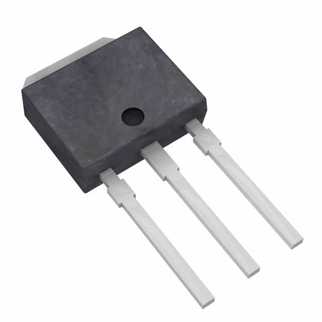
The IRLU110ATU is an N-Channel MOSFET manufactured by onsemi, rated for 100V drain-to-source voltage with 4.7A continuous drain current. The device is packaged in a Through Hole I-PAK (TO-251-3) configuration and is designed for general-purpose switching applications requiring moderate power dissipation capability.
The IRLU110ATU is classified as obsolete. Identifying equivalent and substitute parts is necessary to maintain design continuity, ensure supply chain availability, and support ongoing production requirements for applications currently utilizing this component.
Substiute Parts
Key Parameters
| Parameter | Value | Unit |
|---|---|---|
| Drain-to-Source Voltage (Vdss) | 100 | V |
| Continuous Drain Current (Id) @ 25°C | 4.7 | A |
| On-State Resistance (Rds On Max) @ 5V | 440 | mOhm |
| Gate Threshold Voltage (Vgs(th)) @ 250µA | 2 | V |
| Power Dissipation (Ta) | 2.5 | W |
| Power Dissipation (Tc) | 22 | W |
| Operating Temperature Range | -55 to 150 | °C |
| Package Type | TO-251-3 (I-PAK) | Through Hole |
| Gate Charge (Qg) @ 5V | 8 | nC |
| Input Capacitance (Ciss) @ 25V | 235 | pF |
Substitute Part Grouping Explanation
Substitution of the IRLU110ATU is determined by the following critical electrical and mechanical parameters:
Electrical Compatibility Criteria:
- Drain-to-Source Voltage (Vdss) must equal or exceed 100V
- Continuous Drain Current (Id) must meet or exceed 4.7A at 25°C
- On-State Resistance (Rds On) must not exceed 440mOhm at the specified gate voltage and current
- Gate Threshold Voltage (Vgs(th)) must be compatible with 2V @ 250µA
- Operating temperature range must encompass -55°C to 150°C
Mechanical Compatibility Criteria:
- Package type must be TO-251-3 (I-PAK) Through Hole configuration
- Pin configuration must be identical (3-pin TO-251AA)
- Mounting type must be Through Hole
Functional Compatibility:
- FET Type: N-Channel
- Technology: MOSFET (Metal Oxide Semiconductor)
The substitute parts identified below meet these criteria within the allowed parameter tolerances for direct functional replacement.
Parameter Comparison
| Parameter | IRLU110ATU (onsemi) | IRLU110 (Vishay) | IRLU110PBF (Vishay) |
|---|---|---|---|
| Manufacturer | onsemi | Vishay Siliconix | Vishay Siliconix |
| Product Status | Obsolete | Active | Active |
| Vdss (V) | 100 | 100 | 100 |
| Id @ 25°C (A) | 4.7 | 4.3 | 4.3 |
| Rds On Max @ 5V (mOhm) | 440 @ 2.35A | 540 @ 2.6A | 540 @ 2.6A |
| Vgs(th) @ 250µA (V) | 2 | 2 | 2 |
| Gate Charge Qg @ 5V (nC) | 8 | 6.1 | 6.1 |
| Ciss @ 25V (pF) | 235 | 250 | 250 |
| Power Dissipation Ta (W) | 2.5 | 2.5 | 2.5 |
| Power Dissipation Tc (W) | 22 | 25 | 25 |
| Operating Temperature (°C) | -55 to 150 | -55 to 150 | -55 to 150 |
| Package | TO-251-3 (I-PAK) | TO-251-3 (I-PAK) | TO-251-3 (I-PAK) |
| Mounting Type | Through Hole | Through Hole | Through Hole |
| RoHS Status | REACH Unaffected | RoHS non-compliant | ROHS3 Compliant |
Engineering Selection Recommendations
IRLU110 (Vishay Siliconix) - Active Status
The IRLU110 is an active product from Vishay Siliconix with identical electrical ratings and package configuration to the IRLU110ATU. This part meets all electrical and mechanical substitution criteria. The continuous drain current specification of 4.3A is lower than the IRLU110ATU's 4.7A; however, this represents a conservative design margin for applications operating below 4.3A. The on-state resistance of 540mOhm is higher than the IRLU110ATU's 440mOhm, which may result in increased power dissipation in high-current applications. The IRLU110 is RoHS non-compliant and should be selected only when RoHS compliance is not a design requirement.
IRLU110PBF (Vishay Siliconix) - Active Status, ROHS3 Compliant
The IRLU110PBF is the preferred substitute for the obsolete IRLU110ATU. This part is manufactured by Vishay Siliconix and maintains identical electrical specifications and package configuration. The IRLU110PBF is ROHS3 compliant, making it suitable for applications with environmental and regulatory compliance requirements. The part is supplied in Tube packaging. Electrical performance characteristics are identical to the IRLU110, with the same current and resistance considerations noted above. The IRLU110PBF is recommended as the primary replacement for new designs and ongoing production support.
Frequently Asked Questions (FAQ)
Q: Can the IRLU110 or IRLU110PBF be used as direct replacements for the IRLU110ATU?
A: Yes. Both the IRLU110 and IRLU110PBF are direct functional replacements for the IRLU110ATU. All three devices share identical drain-to-source voltage ratings (100V), gate threshold voltage specifications (2V @ 250µA), operating temperature ranges (-55°C to 150°C), and TO-251-3 package configurations. Pin-to-pin compatibility is maintained across all three parts.
Q: What is the difference between IRLU110 and IRLU110PBF?
A: The IRLU110 and IRLU110PBF are electrically identical. The primary differences are packaging format and RoHS compliance status. The IRLU110PBF is supplied in Tube packaging and is ROHS3 compliant, while the IRLU110 is RoHS non-compliant. For applications requiring environmental compliance certification, the IRLU110PBF is the appropriate selection.
Q: Are there current rating differences between the IRLU110ATU and its substitutes?
A: Yes. The IRLU110ATU is rated for 4.7A continuous drain current, while both the IRLU110 and IRLU110PBF are rated for 4.3A. Applications requiring continuous drain currents between 4.3A and 4.7A must be evaluated to determine if the lower rating of the substitute parts is acceptable. For applications operating below 4.3A, the substitutes are fully compatible.
Q: How do the on-state resistance specifications compare?
A: The IRLU110ATU specifies a maximum on-state resistance of 440mOhm at 2.35A and 5V gate voltage. The IRLU110 and IRLU110PBF specify 540mOhm at 2.6A and 5V gate voltage. The higher resistance of the substitute parts will result in increased power dissipation. Applications with tight thermal budgets or high switching frequencies should account for this difference in design calculations.
Q: Is the package configuration identical across all three parts?
A: Yes. All three parts use the TO-251-3 Short Leads package configuration (I-PAK, TO-251AA) with Through Hole mounting. PCB layouts and thermal management designs developed for the IRLU110ATU are directly compatible with the IRLU110 and IRLU110PBF without modification.
Q: Which substitute part should be selected for new designs?
A: The IRLU110PBF is recommended for new designs. This part is actively manufactured, ROHS3 compliant, and maintains full electrical and mechanical compatibility with the obsolete IRLU110ATU. The ROHS3 compliance status ensures compatibility with current environmental and regulatory standards.
Q: What is the gate charge difference, and does it affect circuit design?
A: The IRLU110ATU specifies 8nC gate charge at 5V, while the IRLU110 and IRLU110PBF specify 6.1nC. The lower gate charge of the substitute parts indicates faster switching response and lower gate drive power requirements. This difference is beneficial for most applications and does not require circuit redesign.
Alternative Parts

SJ6012L2TP
Littelfuse Inc.
6 Alternative Parts

JMK107BBJ476MA-RE
Taiyo Yuden
10 Alternative Parts

GMK107BBJ475MA-T
Taiyo Yuden
5 Alternative Parts
SJ6020N2ARP
Littelfuse Inc.
3 Alternative Parts
SJ6025R2ATP
Littelfuse Inc.
4 Alternative Parts

2474-05L
API Delevan Inc.
1 Alternative Parts

4590R-684K
API Delevan Inc.
1 Alternative Parts

CM6560R-334
API Delevan Inc.
1 Alternative Parts

CM6460-104
API Delevan Inc.
1 Alternative Parts

5526-12
API Delevan Inc.
1 Alternative Parts