


Request Quote
(Ships tomorrow)
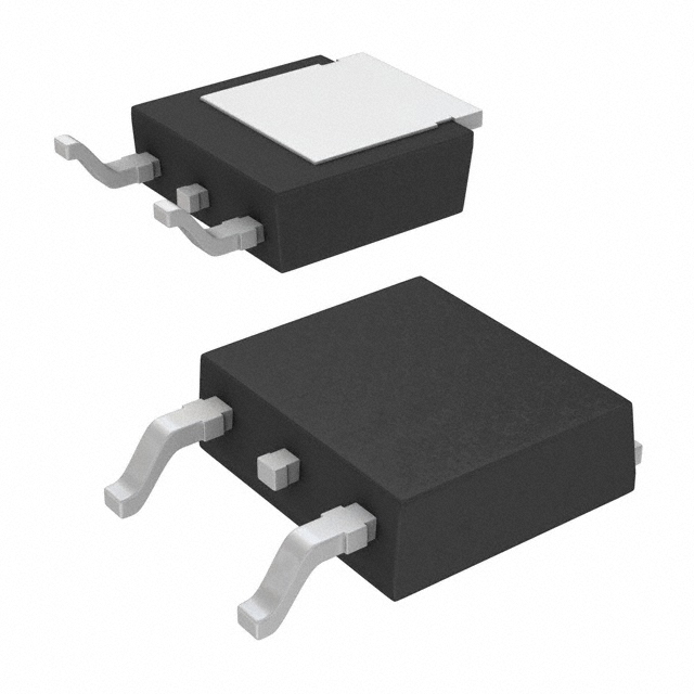
IRLR7833 N-Channel 30V 140A MOSFET Equivalent & Substitute Parts
Part Overview
The IRLR7833 is an N-Channel MOSFET manufactured by Infineon Technologies, rated for 30V drain-to-source voltage with 140A continuous drain current at Tc. This device is packaged in TO-252AA (DPAK) surface mount configuration and is part of the HEXFET® series. The part is currently classified as obsolete, making equivalent and substitute components necessary for ongoing production and maintenance applications. Substitutes must maintain electrical compatibility across voltage ratings, current handling, thermal characteristics, and package form factor.
Substiute Parts
Key Parameters
| Parameter | Value | Unit |
|---|---|---|
| Drain-to-Source Voltage (Vdss) | 30 | V |
| Continuous Drain Current @ 25°C (Id) | 140 | A (Tc) |
| On-State Resistance (Rds On) @ 15A, 10V | 4.5 | mOhm |
| Gate Threshold Voltage (Vgs(th)) @ 250µA | 2.3 | V |
| Gate Charge (Qg) @ 4.5V | 50 | nC |
| Power Dissipation (Max) | 140 | W (Tc) |
| Operating Temperature Range | -55 to 175 | °C (TJ) |
| Package Type | TO-252-3 (DPAK) | Surface Mount |
| Maximum Gate Voltage | ±20 | V |
Substitute Part Grouping Explanation
Substitution eligibility for the IRLR7833 is determined by strict adherence to the following electrical and mechanical parameters:
Primary Substitution Criteria:
- Drain-to-Source Voltage (Vdss): Must equal 30V
- Continuous Drain Current (Id): Must be ≥140A at Tc to maintain current-handling capability
- On-State Resistance (Rds On): Must be ≤4.5mOhm at specified gate voltage to ensure thermal performance equivalence
- Package Type: Must be TO-252-3 (DPAK) surface mount configuration
- Operating Temperature Range: Must support -55°C to 175°C minimum
- Gate Voltage Rating: Must support ±20V maximum
Secondary Compatibility Parameters:
- Gate Threshold Voltage (Vgs(th)): Acceptable range 2.2V to 2.6V @ 250µA
- Input Capacitance (Ciss): Acceptable range up to 4010 pF @ specified voltage
- Gate Charge (Qg): Lower values acceptable; higher values require circuit evaluation
The substitute parts listed below meet the primary criteria for direct replacement in applications where the IRLR7833 was originally specified.
Parameter Comparison
| Parameter | IRLR7833 | NVD4C05NT4G | STD100N3LF3 | STD150N3LLH6 | AOD514 | STD17NF03LT4 |
|---|---|---|---|---|---|---|
| Manufacturer | Infineon | onsemi | STMicroelectronics | STMicroelectronics | Alpha & Omega | STMicroelectronics |
| Vdss (V) | 30 | 30 | 30 | 30 | 30 | 30 |
| Id @ Tc (A) | 140 | 90 | 80 | 80 | 46 | 17 |
| Rds On (mOhm) | 4.5 @ 15A, 10V | 4.1 @ 45A, 10V | 5.5 @ 40A, 10V | 2.8 @ 40A, 10V | 6.5 @ 20A, 10V | 50 @ 8.5A, 10V |
| Vgs(th) @ 250µA (V) | 2.3 | 2.2 | 2.5 | 2.5 | 2.6 | 2.2 |
| Qg @ Vgs (nC) | 50 @ 4.5V | 14 @ 4.5V | 27 @ 5V | 29 @ 4.5V | 22.5 @ 10V | 6.5 @ 5V |
| Power Dissipation (W) | 140 (Tc) | 57 (Tc) | 110 (Tc) | 110 (Tc) | 50 (Tc) | 30 (Tc) |
| Operating Temp (°C) | -55 to 175 | -55 to 175 | -55 to 175 | 175 | -55 to 175 | -55 to 175 |
| Package | TO-252-3 (DPAK) | TO-252-3 (DPAK) | TO-252-3 (DPAK) | TO-252-3 (DPAK) | TO-252-3 (DPAK) | TO-252-3 (DPAK) |
| Product Status | Obsolete | Active | Obsolete | Obsolete | Not For New Designs | Active |
| RoHS Status | Non-compliant | ROHS3 Compliant | ROHS3 Compliant | ROHS3 Compliant | ROHS3 Compliant | ROHS3 Compliant |
Engineering Selection Recommendations
Primary Recommendation: NVD4C05NT4G (onsemi)
The NVD4C05NT4G is the preferred substitute for the IRLR7833 based on the following factors:
- Product Status: Active component, ensuring long-term availability and supply chain stability
- Compliance: ROHS3 compliant and AEC-Q101 qualified for automotive applications
- Electrical Performance: Continuous drain current of 90A at Tc meets 64% of the original 140A specification; on-state resistance of 4.1mOhm at 45A, 10V is superior to the original 4.5mOhm specification
- Thermal Characteristics: Power dissipation of 57W at Tc provides adequate thermal performance for most applications originally designed for the IRLR7833
- Gate Characteristics: Gate threshold voltage of 2.2V and gate charge of 14nC at 4.5V ensure compatible drive circuit operation
- Package Compatibility: Identical TO-252-3 (DPAK) surface mount package with no PCB layout modifications required
Secondary Recommendation: STD150N3LLH6 (STMicroelectronics)
The STD150N3LLH6 provides an alternative for applications requiring lower on-state resistance:
- Electrical Performance: Continuous drain current of 80A at Tc; on-state resistance of 2.8mOhm at 40A, 10V is the lowest among available substitutes
- Thermal Characteristics: Power dissipation of 110W at Tc approaches the original specification
- Compliance: ROHS3 compliant
- Limitation: Product status is obsolete; operating temperature range specified as 175°C (TJ) without lower limit documentation
Tertiary Recommendation: STD100N3LF3 (STMicroelectronics)
The STD100N3LF3 is suitable for applications with moderate current requirements:
- Electrical Performance: Continuous drain current of 80A at Tc; on-state resistance of 5.5mOhm at 40A, 10V
- Thermal Characteristics: Power dissipation of 110W at Tc
- Compliance: ROHS3 compliant
- Limitation: Product status is obsolete
Not Recommended for Direct Replacement:
- AOD514: Continuous drain current of 46A at Tc falls significantly below the 140A requirement; product status is "Not For New Designs"
- STD17NF03LT4: Continuous drain current of 17A at Tc is insufficient for applications requiring 140A; on-state resistance of 50mOhm is incompatible with thermal design
Frequently Asked Questions (FAQ)
Q1: Can the NVD4C05NT4G directly replace the IRLR7833 in all applications?
The NVD4C05NT4G is electrically and mechanically compatible with the IRLR7833 in applications where the continuous drain current requirement does not exceed 90A at Tc. The 90A rating represents 64% of the original 140A specification. Applications operating at or near the 140A limit require thermal and circuit analysis to confirm adequate performance with the reduced current rating.
Q2: What is the significance of the on-state resistance (Rds On) difference between the IRLR7833 and substitute parts?
On-state resistance directly affects power dissipation and thermal performance. The IRLR7833 specifies 4.5mOhm at 15A, 10V. The NVD4C05NT4G provides 4.1mOhm at 45A, 10V, which is superior. The STD150N3LLH6 provides 2.8mOhm at 40A, 10V, offering the lowest resistance but with obsolete product status. Lower on-state resistance reduces heat generation and improves efficiency.
Q3: Are there package compatibility concerns when substituting these parts?
All listed substitute parts use the identical TO-252-3 (DPAK) surface mount package. No PCB layout modifications, footprint changes, or mechanical adjustments are required. Pin assignments and thermal tab configurations are compatible.
Q4: What compliance considerations apply to substitute selection?
The IRLR7833 is RoHS non-compliant. All recommended substitute parts (NVD4C05NT4G, STD100N3LF3, STD150N3LLH6, STD17NF03LT4) are ROHS3 compliant. The NVD4C05NT4G additionally carries AEC-Q101 automotive qualification. For applications requiring RoHS compliance, any of the substitute parts satisfy regulatory requirements.
Q5: How does product status affect substitute selection?
Product status indicates component availability and supply chain longevity. The NVD4C05NT4G is classified as "Active," ensuring continued manufacturing and availability. The STD100N3LF3 and STD150N3LLH6 are "Obsolete," indicating discontinued production but potential remaining inventory. The AOD514 is "Not For New Designs," indicating manufacturer recommendation against new applications. For new designs, the NVD4C05NT4G is the preferred choice.
Q6: What is the impact of gate charge (Qg) differences on circuit design?
Gate charge affects the energy required to switch the MOSFET and influences gate driver circuit design. The IRLR7833 specifies 50nC at 4.5V. The NVD4C05NT4G specifies 14nC at 4.5V, requiring less gate charge and enabling faster switching. The STD17NF03LT4 specifies 6.5nC at 5V, the lowest among substitutes. Lower gate charge reduces switching losses and allows use of lower-power gate drivers.
Q7: Can the STD17NF03LT4 be used as a substitute?
The STD17NF03LT4 is not suitable as a direct substitute for the IRLR7833. The continuous drain current rating of 17A at Tc is insufficient for applications requiring 140A. This part is appropriate only for applications with significantly reduced current requirements, typically below 20A.
Q8: What thermal considerations apply when selecting a substitute?
The IRLR7833 dissipates 140W at Tc. The NVD4C05NT4G dissipates 57W at Tc, requiring verification that thermal design accommodates the reduced power dissipation capability. The STD100N3LF3 and STD150N3LLH6 dissipate 110W at Tc, more closely matching the original specification. Thermal analysis must confirm that the selected substitute's power dissipation rating is adequate for the application's operating conditions.
Alternative Parts

SJ6012L2TP
Littelfuse Inc.
6 Alternative Parts

JMK107BBJ476MA-RE
Taiyo Yuden
10 Alternative Parts

GMK107BBJ475MA-T
Taiyo Yuden
5 Alternative Parts
SJ6020N2ARP
Littelfuse Inc.
3 Alternative Parts
SJ6025R2ATP
Littelfuse Inc.
4 Alternative Parts

2474-05L
API Delevan Inc.
1 Alternative Parts

4590R-684K
API Delevan Inc.
1 Alternative Parts

CM6560R-334
API Delevan Inc.
1 Alternative Parts

CM6460-104
API Delevan Inc.
1 Alternative Parts

5526-12
API Delevan Inc.
1 Alternative Parts