


Request Quote
(Ships tomorrow)
IRLR7807ZCPBF N-Channel 30V 43A MOSFET Equivalent & Substitute Parts
Part Overview
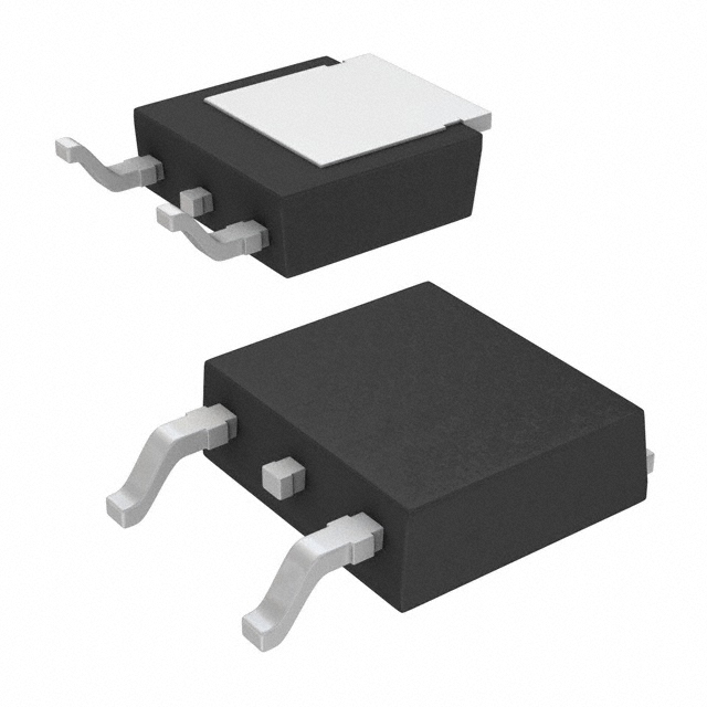
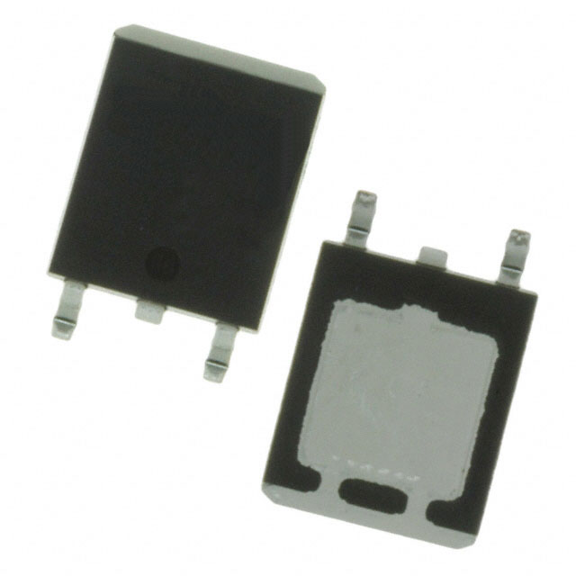
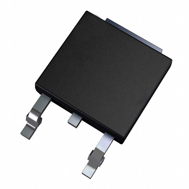
The IRLR7807ZCPBF is an N-Channel MOSFET manufactured by Infineon Technologies, rated for 30V drain-to-source voltage and 43A continuous drain current in a surface mount TO-252AA (DPAK) package. This device is classified as obsolete, making equivalent and substitute parts necessary for ongoing design support, production continuity, and component sourcing.
The IRLR7807ZCPBF belongs to the HEXFET® series and is designed for applications requiring moderate to high current switching at 30V operating levels. As an obsolete component, alternative N-Channel MOSFETs with compatible electrical and mechanical specifications must be evaluated for direct substitution or design adaptation.
Substiute Parts
Key Parameters
| Parameter | Value | Unit | Condition |
|---|---|---|---|
| Drain-to-Source Voltage (Vdss) | 30 | V | Maximum rating |
| Continuous Drain Current (Id) | 43 | A | @ 25°C (Tc) |
| On-State Resistance (Rds On) | 13.8 | mOhm | @ 15A, 10V Vgs |
| Gate Threshold Voltage (Vgs(th)) | 2.25 | V | @ 250µA |
| Gate Charge (Qg) | 11 | nC | @ 4.5V |
| Input Capacitance (Ciss) | 780 | pF | @ 15V Vds |
| Power Dissipation | 40 | W | @ Tc |
| Operating Temperature Range | -55 to 175 | °C | Junction temperature (TJ) |
| Package Type | TO-252-3 (DPAK) | — | Surface mount, 2 leads + tab |
| Moisture Sensitivity Level | 1 | — | Unlimited shelf life |
Substitute Part Grouping Explanation
Substitution of the IRLR7807ZCPBF is determined by strict alignment of the following electrical and mechanical parameters:
Primary Substitution Criteria:
- Drain-to-Source Voltage (Vdss): Must equal 30V
- Package Type: Must be TO-252-3 (DPAK) or mechanically compatible surface mount package
- FET Type: Must be N-Channel MOSFET
- Technology: Metal Oxide Semiconductor (MOSFET)
- Mounting: Surface mount only
Secondary Compatibility Parameters:
- Continuous Drain Current (Id): Substitute must meet or exceed 43A @ 25°C
- On-State Resistance (Rds On): Lower or equal values indicate improved performance
- Gate Threshold Voltage (Vgs(th)): Must fall within ±20V maximum gate voltage specification
- Operating Temperature Range: Must support -55°C to 175°C minimum
- Moisture Sensitivity: MSL 1 (unlimited) preferred for storage flexibility
Substitutes are grouped into three categories:
- Direct Equivalents – Identical or superior electrical ratings with same package footprint
- Functional Alternatives – Different current ratings or package variants requiring design verification
- Obsolete Alternatives – Substitute parts also classified as obsolete; use only when active alternatives unavailable
Parameter Comparison
| Part Number | Manufacturer | Vdss (V) | Id @ 25°C (A) | Rds On (mOhm) | Vgs(th) (V) | Qg (nC) | Ciss (pF) | Package | Status |
|---|---|---|---|---|---|---|---|---|---|
| IRLR7807ZCPBF | Infineon | 30 | 43 (Tc) | 13.8 @ 15A, 10V | 2.25 @ 250µA | 11 @ 4.5V | 780 @ 15V | TO-252AA (DPAK) | Obsolete |
| IPD135N03LGATMA1 | Infineon | 30 | 30 (Tc) | 13.5 @ 30A, 10V | 2.2 @ 250µA | 10 @ 10V | 1000 @ 15V | PG-TO252-3 (DPAK) | Active |
| ATP202-TL-H | onsemi | 30 | 50 (Ta) | 12 @ 25A, 10V | Not specified | 27 @ 10V | 1650 @ 10V | ATPAK | Obsolete |
| DMN3016LK3-13 | Diodes Inc. | 30 | 12.4 (Ta) | 12 @ 11A, 10V | 2.3 @ 250µA | 25.1 @ 10V | 1415 @ 15V | TO-252-3 (DPAK) | Active |
| FDD6690A | onsemi | 30 | 12 (Ta), 46 (Tc) | 12 @ 12A, 10V | 3 @ 250µA | 18 @ 5V | 1230 @ 15V | TO-252AA (DPAK) | Obsolete |
| STD100N3LF3 | STMicroelectronics | 30 | 80 (Tc) | 5.5 @ 40A, 10V | 2.5 @ 250µA | 27 @ 5V | 2060 @ 25V | DPAK | Obsolete |
| STD150N3LLH6 | STMicroelectronics | 30 | 80 (Tc) | 2.8 @ 40A, 10V | 2.5 @ 250µA | 29 @ 4.5V | 3700 @ 25V | DPAK | Obsolete |
Engineering Selection Recommendations
For Active Component Sourcing:
The IPD135N03LGATMA1 (Infineon, Active status) is the primary recommended substitute. Although rated at 30A continuous drain current versus the original 43A, it maintains identical 30V Vdss rating, compatible TO-252-3 DPAK package footprint, and superior on-state resistance (13.5 mOhm). This part is manufactured by the same supplier as the original IRLR7807ZCPBF and carries ROHS3 compliance certification. The reduced current rating requires thermal and circuit analysis to confirm adequacy for target application.
The DMN3016LK3-13 (Diodes Incorporated, Active status) provides an alternative from a different manufacturer. This part is rated at 12.4A continuous current and is suitable only for applications with significantly lower current requirements than the original 43A specification. It maintains 30V Vdss, TO-252-3 DPAK package compatibility, and ROHS3 compliance.
For Obsolete Component Replacement (When Active Alternatives Insufficient):
The ATP202-TL-H (onsemi, Obsolete) offers 50A continuous drain current, exceeding the original 43A rating. However, it uses ATPAK package, requiring PCB layout modification. The STD100N3LF3 and STD150N3LLH6 (both STMicroelectronics, Obsolete) provide 80A ratings with superior on-state resistance but require thermal management verification due to increased power dissipation capability.
The FDD6690A (onsemi, Obsolete) provides dual current ratings (12A Ta / 46A Tc) and maintains TO-252AA DPAK package compatibility with the original part.
Compliance and Certification:
All substitute parts listed carry ROHS3 compliance and REACH Unaffected status, matching the original part's regulatory standing. Moisture Sensitivity Level 1 (unlimited) is maintained across all active alternatives, ensuring storage and handling compatibility.
Frequently Asked Questions (FAQ)
Q: Can the IPD135N03LGATMA1 directly replace the IRLR7807ZCPBF in all applications?
A: Direct replacement requires verification that the application does not demand the full 43A continuous current rating. The IPD135N03LGATMA1 is rated at 30A continuous drain current. Thermal analysis of the circuit must confirm that peak and sustained current demands remain below 30A. Package footprint compatibility is confirmed (both TO-252-3 DPAK).
Q: Why do some substitute parts have different package designations (ATPAK vs. DPAK)?
A: Package differences indicate different physical footprints and pin configurations. The ATP202-TL-H uses ATPAK package, which is not mechanically compatible with TO-252-3 DPAK without PCB redesign. Parts with identical package designations (TO-252-3 DPAK) are mechanically interchangeable without layout modification.
Q: What is the significance of the Rds On (on-state resistance) differences between parts?
A: Lower Rds On values result in reduced power dissipation during conduction. The STD150N3LLH6 exhibits 2.8 mOhm Rds On compared to the original 13.8 mOhm, indicating superior efficiency but requiring verification that the application circuit can tolerate the different switching characteristics and gate charge requirements.
Q: Are all substitute parts suitable for the full -55°C to 175°C operating temperature range?
A: The IPD135N03LGATMA1 and DMN3016LK3-13 (active parts) support -55°C to 175°C and -55°C to 150°C respectively. The DMN3016LK3-13 has a reduced upper temperature limit of 150°C. Verify application requirements against each part's specified operating temperature range.
Q: What does "Obsolete" product status mean for substitute selection?
A: Obsolete status indicates the manufacturer has discontinued production and support. Obsolete substitute parts should be selected only when active alternatives cannot meet application requirements. Inventory availability for obsolete parts is finite and may diminish over time.
Q: How do gate charge (Qg) differences affect circuit design?
A: Gate charge determines the energy required to switch the MOSFET on and off. Higher Qg values (e.g., ATP202-TL-H at 27 nC) require more gate drive current and may necessitate driver circuit modifications. Lower Qg values (e.g., IPD135N03LGATMA1 at 10 nC) reduce gate drive requirements.
Q: Can I use a substitute part with higher current rating than the original?
A: Yes, provided the application circuit and thermal design accommodate the different electrical characteristics. Higher-rated parts typically exhibit different Rds On, gate charge, and input capacitance values that may affect switching speed, efficiency, and thermal performance. Circuit simulation and prototype testing are required.
Q: What is the importance of Moisture Sensitivity Level (MSL) matching?
A: MSL 1 (unlimited) indicates the component has no moisture sensitivity restrictions and can be stored indefinitely without special drying procedures. All listed substitutes maintain MSL 1, ensuring compatibility with existing supply chain and storage protocols.
Alternative Parts

SJ6012L2TP
Littelfuse Inc.
6 Alternative Parts

JMK107BBJ476MA-RE
Taiyo Yuden
10 Alternative Parts

GMK107BBJ475MA-T
Taiyo Yuden
5 Alternative Parts
SJ6020N2ARP
Littelfuse Inc.
3 Alternative Parts
SJ6025R2ATP
Littelfuse Inc.
4 Alternative Parts

2474-05L
API Delevan Inc.
1 Alternative Parts

4590R-684K
API Delevan Inc.
1 Alternative Parts

CM6560R-334
API Delevan Inc.
1 Alternative Parts

CM6460-104
API Delevan Inc.
1 Alternative Parts

5526-12
API Delevan Inc.
1 Alternative Parts