


Request Quote
(Ships tomorrow)
IRLR3715ZTRLPBF Equivalent & Substitute Parts
Part Overview
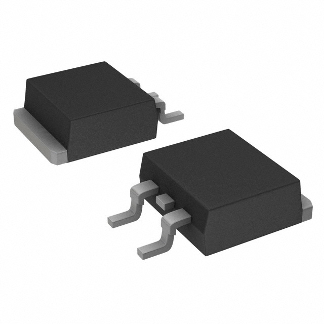
The IRLR3715ZTRLPBF is an N-Channel MOSFET manufactured by Infineon Technologies, rated for 20V drain-to-source voltage with 49A continuous drain current at 25°C. This device is housed in a TO-252AA (DPAK) surface mount package and is designed for applications requiring moderate voltage switching with high current handling capability.
The IRLR3715ZTRLPBF is classified as obsolete. Identifying equivalent and substitute parts is necessary to maintain design continuity, ensure supply chain availability, and support ongoing production requirements for legacy systems or redesign initiatives.
Substiute Parts
Key Parameters
| Parameter | Value | Unit |
|---|---|---|
| Drain to Source Voltage (Vdss) | 20 | V |
| Continuous Drain Current (Id) @ 25°C | 49 | A (Tc) |
| Rds On (Max) @ Id, Vgs | 11 | mOhm @ 15A, 10V |
| Gate Threshold Voltage Vgs(th) (Max) @ Id | 2.55 | V @ 250µA |
| Gate Charge (Qg) (Max) @ Vgs | 11 | nC @ 4.5V |
| Input Capacitance (Ciss) (Max) @ Vds | 810 | pF @ 10V |
| Power Dissipation (Max) | 40 | W (Tc) |
| Operating Temperature Range | -55 to 175 | °C (TJ) |
| Package Type | TO-252-3 (DPAK) | Surface Mount |
| Moisture Sensitivity Level (MSL) | 1 | Unlimited |
Substitute Part Grouping Explanation
Substitution of the IRLR3715ZTRLPBF is determined by strict alignment of the following electrical and mechanical parameters:
Critical Matching Parameters:
- FET Type: N-Channel MOSFET technology
- Drain to Source Voltage (Vdss): Minimum 20V rating required
- Continuous Drain Current (Id): 49A at 25°C (Tc)
- Package Type: TO-252AA (DPAK) surface mount configuration
- Operating Temperature Range: -55°C to 175°C (TJ)
- Mounting Type: Surface Mount
Functional Compatibility Parameters:
- Rds On (Max): Must not exceed specified on-resistance at rated conditions
- Gate Threshold Voltage: Must fall within acceptable switching characteristics
- Gate Charge and Input Capacitance: Must support existing gate drive circuitry
The substitute part SUD50N024-09P-E3 meets all critical matching parameters. The Vdss rating of 22V exceeds the minimum 20V requirement, providing additional voltage margin. The continuous drain current of 49A matches the original specification exactly. Both devices utilize identical TO-252AA packaging and support the same operating temperature range.
Parameter Comparison
| Parameter | IRLR3715ZTRLPBF (Main Part) | SUD50N024-09P-E3 (Substitute) | Unit |
|---|---|---|---|
| Manufacturer | Infineon Technologies | Vishay Siliconix | — |
| FET Type | N-Channel | N-Channel | — |
| Drain to Source Voltage (Vdss) | 20 | 22 | V |
| Continuous Drain Current (Id) @ 25°C | 49 | 49 | A (Tc) |
| Rds On (Max) @ Id, Vgs | 11 @ 15A, 10V | 9.5 @ 20A, 10V | mOhm |
| Gate Threshold Voltage Vgs(th) (Max) @ Id | 2.55 @ 250µA | 3 @ 250µA | V |
| Gate Charge (Qg) (Max) @ Vgs | 11 @ 4.5V | 16 @ 4.5V | nC |
| Input Capacitance (Ciss) (Max) @ Vds | 810 @ 10V | 1300 @ 10V | pF |
| Power Dissipation (Max) | 40 (Tc) | 39.5 (Tc) | W |
| Operating Temperature Range | -55 to 175 | -55 to 175 | °C (TJ) |
| Package Type | TO-252-3 (DPAK) | TO-252-3 (DPAK) | — |
| Mounting Type | Surface Mount | Surface Mount | — |
| Moisture Sensitivity Level (MSL) | 1 (Unlimited) | 1 (Unlimited) | — |
| Product Status | Obsolete | Active | — |
Engineering Selection Recommendations
SUD50N024-09P-E3 as Primary Substitute:
The SUD50N024-09P-E3 is the manufacturer-recommended substitute for the IRLR3715ZTRLPBF. This device is classified as Active product status, ensuring ongoing availability and supply chain support. The substitute meets all critical electrical parameters required for functional equivalence:
- Vdss rating of 22V provides 2V additional voltage margin above the original 20V specification
- Continuous drain current of 49A matches the original device exactly
- Operating temperature range of -55°C to 175°C is identical
- TO-252AA (DPAK) package configuration is mechanically and electrically identical
- Moisture Sensitivity Level (MSL) of 1 (Unlimited) matches the original specification
- RoHS3 compliance status supports modern manufacturing and environmental requirements
Parameter Variations:
The SUD50N024-09P-E3 exhibits the following parameter differences from the IRLR3715ZTRLPBF:
- Rds On is lower (9.5 mOhm @ 20A, 10V versus 11 mOhm @ 15A, 10V), indicating improved on-state performance
- Gate Threshold Voltage is slightly higher (3V versus 2.55V), representing a minor shift in switching characteristics
- Gate Charge is higher (16 nC versus 11 nC), requiring slightly increased gate drive energy
- Input Capacitance is higher (1300 pF versus 810 pF), affecting gate drive circuit timing
These variations are within acceptable engineering tolerances for N-Channel MOSFET substitution and do not preclude direct replacement in applications designed for the IRLR3715ZTRLPBF.
Frequently Asked Questions (FAQ)
Q: Can the SUD50N024-09P-E3 be used as a direct replacement for the IRLR3715ZTRLPBF?
A: Yes. Both devices are N-Channel MOSFETs with identical continuous drain current (49A), matching operating temperature range (-55°C to 175°C), and identical TO-252AA (DPAK) surface mount packaging. The SUD50N024-09P-E3 meets all critical electrical and mechanical parameters required for functional equivalence.
Q: What is the significance of the higher Vdss rating (22V) on the substitute part?
A: The higher Vdss rating of 22V on the SUD50N024-09P-E3 provides additional voltage margin compared to the original 20V specification. This allows the substitute to operate safely in applications with transient voltage spikes or design margin requirements. The higher rating does not negatively impact performance in circuits designed for 20V operation.
Q: How do the gate charge differences affect circuit design?
A: The SUD50N024-09P-E3 has a higher gate charge (16 nC @ 4.5V) compared to the IRLR3715ZTRLPBF (11 nC @ 4.5V). This requires approximately 45% more charge to drive the gate to the specified voltage. Existing gate drive circuits must supply sufficient current to charge the gate within the required switching time. Gate drive circuits with adequate current capacity will accommodate this difference without modification.
Q: Are there thermal performance differences between these devices?
A: Both devices have nearly identical maximum power dissipation ratings (40W for IRLR3715ZTRLPBF and 39.5W for SUD50N024-09P-E3 at Tc). The SUD50N024-09P-E3 exhibits lower on-state resistance (9.5 mOhm versus 11 mOhm), which may result in slightly lower conduction losses in high-current applications. Thermal management requirements remain equivalent.
Q: Does the higher input capacitance of the substitute affect switching speed?
A: The SUD50N024-09P-E3 has higher input capacitance (1300 pF @ 10V versus 810 pF @ 10V). Higher input capacitance increases the RC time constant in gate drive circuits, potentially extending switching transition times. Gate drive circuits with sufficient current capacity will maintain acceptable switching performance. Applications with strict switching speed requirements should verify gate drive circuit performance with the substitute device.
Q: What is the product status significance?
A: The IRLR3715ZTRLPBF is classified as Obsolete, indicating discontinued manufacturing and limited availability. The SUD50N024-09P-E3 is classified as Active, ensuring ongoing production, supply chain availability, and manufacturer support. Transitioning to the active substitute part ensures long-term design sustainability.
Q: Are there compliance or certification differences?
A: The SUD50N024-09P-E3 carries RoHS3 compliance certification, supporting modern manufacturing and environmental regulatory requirements. Both devices have identical Moisture Sensitivity Level (MSL) of 1 (Unlimited) and identical ECCN and HTSUS classifications, indicating equivalent handling and regulatory status.
Alternative Parts

SJ6012L2TP
Littelfuse Inc.
6 Alternative Parts

JMK107BBJ476MA-RE
Taiyo Yuden
10 Alternative Parts

GMK107BBJ475MA-T
Taiyo Yuden
5 Alternative Parts
SJ6020N2ARP
Littelfuse Inc.
3 Alternative Parts
SJ6025R2ATP
Littelfuse Inc.
4 Alternative Parts

2474-05L
API Delevan Inc.
1 Alternative Parts

4590R-684K
API Delevan Inc.
1 Alternative Parts

CM6560R-334
API Delevan Inc.
1 Alternative Parts

CM6460-104
API Delevan Inc.
1 Alternative Parts

5526-12
API Delevan Inc.
1 Alternative Parts