


Request Quote
(Ships tomorrow)
IRLR024TRLPBF N-Channel 60V 14A MOSFET Equivalent & Substitute Parts
Part Overview
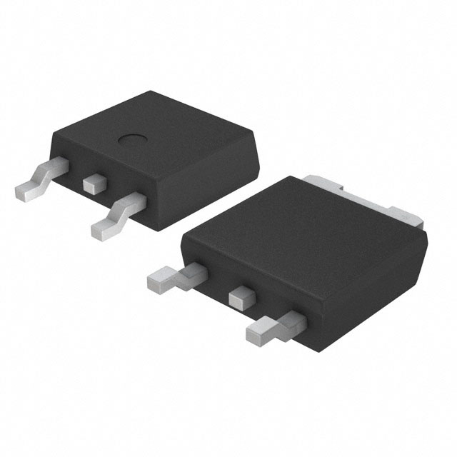
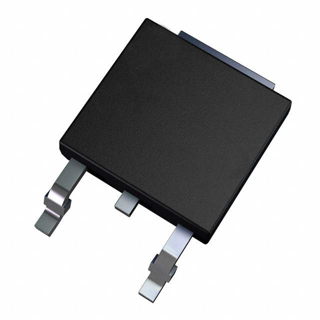
The IRLR024TRLPBF is an N-Channel metal oxide semiconductor field-effect transistor (MOSFET) manufactured by Vishay Siliconix, rated for 60V drain-to-source voltage and 14A continuous drain current. The device is packaged in a surface mount DPAK (TO-252-3) configuration and is designed for general-purpose switching and amplification applications in power electronics circuits.
The IRLR024TRLPBF maintains Active product status with full RoHS3 compliance and unlimited moisture sensitivity level (MSL 1). Equivalent and substitute parts are identified based on matching or exceeding critical electrical parameters including drain-to-source voltage rating, continuous drain current capability, on-resistance characteristics, and thermal performance specifications. Substitutes are selected to ensure functional compatibility within the same package family while maintaining or improving performance margins.
Substiute Parts
Key Parameters
| Parameter | Value | Unit |
|---|---|---|
| Drain-to-Source Voltage (Vdss) | 60 | V |
| Continuous Drain Current (Id) @ 25°C | 14 | A (Tc) |
| On-Resistance (Rds On Max) @ Id, Vgs | 100 mOhm @ 8.4A, 5V | mOhm |
| Gate Threshold Voltage (Vgs(th) Max) @ Id | 2 | V @ 250µA |
| Gate Charge (Qg Max) @ Vgs | 18 | nC @ 5V |
| Input Capacitance (Ciss Max) @ Vds | 870 | pF @ 25V |
| Power Dissipation (Max) | 2.5 (Ta), 42 (Tc) | W |
| Operating Temperature Range | -55 to 150 | °C (TJ) |
| Package Type | TO-252-3, DPAK | Surface Mount |
| FET Type | N-Channel | — |
| Technology | MOSFET (Metal Oxide) | — |
Substitute Part Grouping Explanation
Substitute parts for the IRLR024TRLPBF are classified into two categories based on parametric equivalence and functional compatibility:
Parametric Equivalent (Direct Replacement): Parts that match all critical electrical specifications including Vdss (60V), Id (14A nominal or higher), Rds On characteristics, and package type (DPAK/TO-252-3). These parts are interchangeable without circuit modification.
Functional Substitutes (Application-Dependent): Parts that maintain the same package footprint and general N-Channel MOSFET functionality but may differ in one or more electrical parameters. Selection depends on specific circuit requirements for voltage rating, current handling, or thermal performance.
Key Parameters Determining Substitution Eligibility:
- Drain-to-Source Voltage (Vdss): Must equal or exceed 60V
- Continuous Drain Current (Id): Must equal or exceed 14A at rated conditions
- On-Resistance (Rds On): Lower values preferred; maximum acceptable determined by circuit thermal budget
- Package Type: Must be DPAK/TO-252-3 surface mount configuration
- Gate Threshold Voltage (Vgs(th)): Must be compatible with drive circuit voltage levels
- Operating Temperature Range: Must support application temperature extremes
- RoHS Compliance: Must maintain ROHS3 compliance status
Parameter Comparison
| Part Number | Manufacturer | Vdss (V) | Id (A) | Rds On Max (mOhm) | Vgs(th) Max (V) | Qg Max (nC) | Ciss Max (pF) | Power Diss Max (W) | Temp Range (°C) | Status |
|---|---|---|---|---|---|---|---|---|---|---|
| IRLR024TRLPBF | Vishay Siliconix | 60 | 14 | 100 @ 8.4A, 5V | 2 @ 250µA | 18 @ 5V | 870 @ 25V | 2.5 (Ta), 42 (Tc) | -55 to 150 | Active |
| IRLR024TRPBF | Vishay Siliconix | 60 | 14 | 100 @ 8.4A, 5V | 2 @ 250µA | 18 @ 5V | 870 @ 25V | 2.5 (Ta), 42 (Tc) | -55 to 150 | Active |
| IRLR024NTRPBF | Infineon Technologies | 55 | 17 | 65 @ 10A, 10V | 2 @ 250µA | 15 @ 5V | 480 @ 25V | 45 (Tc) | -55 to 175 | Active |
| FQD13N06LTM | onsemi | 60 | 11 | 115 @ 5.5A, 10V | 2.5 @ 250µA | 6.4 @ 5V | 350 @ 25V | 2.5 (Ta), 28 (Tc) | -55 to 150 | Active |
| FQD16N25CTM | onsemi | 250 | 16 | 270 @ 8A, 10V | 4 @ 250µA | 53.5 @ 10V | 1080 @ 25V | 160 (Tc) | -55 to 150 | Active |
| RFD3055LESM9A | onsemi | 60 | 11 | 107 @ 8A, 5V | 3 @ 250µA | 11.3 @ 10V | 350 @ 25V | 38 (Tc) | -55 to 175 | Active |
| STD12NF06T4 | STMicroelectronics | 60 | 12 | 100 @ 6A, 10V | 4 @ 250µA | 12 @ 10V | 315 @ 25V | 30 (Tc) | -55 to 175 | Active |
| ZXMN7A11KTC | Diodes Incorporated | 70 | 4.2 | 130 @ 4.4A, 10V | 1 @ 250µA | 7.4 @ 10V | 298 @ 40V | 2.11 (Ta) | -55 to 150 | Active |
| FCD4N60TM | onsemi | 600 | 3.9 | 1200 @ 2A, 10V | 5 @ 250µA | 16.6 @ 10V | 540 @ 25V | 50 (Tc) | -55 to 150 | Not For New Designs |
| FDD3N40TM | onsemi | 400 | 2 | 3400 @ 1A, 10V | 5 @ 250µA | 6 @ 10V | 225 @ 25V | 30 (Tc) | -55 to 150 | Active |
| FQD2N100TM | onsemi | 1000 | 1.6 | 9000 @ 800mA, 10V | 5 @ 250µA | 15.5 @ 10V | 520 @ 25V | 2.5 (Ta), 50 (Tc) | -55 to 150 | Active |
Engineering Selection Recommendations
Direct Parametric Equivalent:
The IRLR024TRPBF (Vishay Siliconix) is a direct parametric equivalent to the IRLR024TRLPBF. Both parts share identical electrical specifications, package configuration, and Active product status. The IRLR024TRPBF differs only in packaging format (Tape & Reel vs. Tape & Reel with different reel specification) and maintains full compatibility for circuit-level substitution. Inventory availability is higher for IRLR024TRPBF (15,365 units vs. 2,026 units).
Near-Equivalent Substitutes (Vdss = 60V, Similar Current Rating):
The IRLR024NTRPBF (Infineon Technologies, HEXFET® series) provides superior performance characteristics with 17A continuous drain current (exceeding the 14A requirement), lower on-resistance (65 mOhm vs. 100 mOhm), and extended operating temperature range (-55°C to 175°C vs. -55°C to 150°C). The 55V Vdss rating is slightly lower than the 60V specification but remains within acceptable margins for most 60V-class applications. This part is recommended when improved thermal performance or higher current margin is required.
The STD12NF06T4 (STMicroelectronics, STripFET™ II series) operates at 60V with 12A continuous drain current and 100 mOhm on-resistance. Extended temperature range (-55°C to 175°C) and Active product status support long-term design continuity. Gate charge (12 nC) is lower than the main part, reducing drive circuit power consumption.
The RFD3055LESM9A (onsemi) provides 60V rating with 11A continuous drain current and 107 mOhm on-resistance. Extended temperature range (-55°C to 175°C) and higher power dissipation capability (38W Tc) support thermal-demanding applications.
The FQD13N06LTM (onsemi, QFET® series) operates at 60V with 11A continuous drain current. Lower gate charge (6.4 nC @ 5V) and reduced input capacitance (350 pF) minimize switching losses in high-frequency applications. Active product status ensures design continuity.
Functional Substitutes (Higher Voltage Rating, Lower Current):
The FQD16N25CTM (onsemi, QFET® series) provides 250V Vdss rating with 16A continuous drain current, suitable for applications requiring higher voltage margin. Higher on-resistance (270 mOhm) and gate charge (53.5 nC) reflect the higher voltage class. Active product status and high inventory (26,400 units) support availability.
The FCD4N60TM (onsemi, SuperFET™ series) operates at 600V with 3.9A continuous drain current. This part is designated "Not For New Designs" and is included for legacy system support only. Significantly higher on-resistance (1.2 Ohm) and lower current rating make this unsuitable for new applications matching the IRLR024TRLPBF specification.
The FDD3N40TM (onsemi, UniFET™ series) provides 400V rating with 2A continuous drain current. Substantially higher on-resistance (3.4 Ohm) and lower current capability restrict this part to lower-power applications.
The FQD2N100TM (onsemi, QFET® series) operates at 1000V with 1.6A continuous drain current. Extremely high on-resistance (9 Ohm) and minimal current rating are suitable only for high-voltage, low-current switching applications.
The ZXMN7A11KTC (Diodes Incorporated) provides 70V rating with only 4.2A continuous drain current. Significantly lower current capability and higher on-resistance (130 mOhm) restrict this part to low-current applications and are not recommended as a primary substitute.
Compliance and Certification:
All recommended substitutes maintain ROHS3 compliance and MSL 1 (unlimited) moisture sensitivity level. Parts designated Active product status are preferred for new designs. The FCD4N60TM carries "Not For New Designs" status and should be used only in legacy system maintenance scenarios.
Frequently Asked Questions (FAQ)
Q: Can IRLR024TRPBF be used as a direct replacement for IRLR024TRLPBF?
A: Yes. The IRLR024TRPBF is a parametric equivalent with identical electrical specifications, package type (DPAK/TO-252-3), and Active product status. The parts differ only in packaging format designation. Direct substitution is supported without circuit modification.
Q: What is the primary difference between the IRLR024NTRPBF and the main part?
A: The IRLR024NTRPBF (Infineon) has a 55V Vdss rating versus 60V for the IRLR024TRLPBF, but provides superior current handling (17A vs. 14A) and lower on-resistance (65 mOhm vs. 100 mOhm). The 55V rating is acceptable for 60V-class applications with appropriate design margin verification. Extended temperature range (-55°C to 175°C) supports wider operating environments.
Q: Why is the FQD16N25CTM listed as a substitute if it has a 250V rating?
A: The FQD16N25CTM is included as a functional substitute for applications where higher voltage margin is required. While the 250V rating exceeds the 60V specification, the part maintains the same DPAK package footprint and N-Channel MOSFET topology. Higher on-resistance (270 mOhm) and gate charge (53.5 nC) reflect the higher voltage class. This part is suitable only for circuits designed to accommodate these electrical differences.
Q: Should the FCD4N60TM be used in new designs?
A: No. The FCD4N60TM carries "Not For New Designs" product status and is listed for reference only in legacy system support scenarios. The part's 600V rating, 3.9A current capability, and 1.2 Ohm on-resistance make it unsuitable for applications matching the IRLR024TRLPBF specification. Active alternatives such as IRLR024NTRPBF or STD12NF06T4 are recommended for new designs.
Q: What is the significance of gate charge (Qg) differences between substitutes?
A: Gate charge determines the energy required to switch the MOSFET on and off. Lower gate charge (e.g., FQD13N06LTM at 6.4 nC vs. main part at 18 nC) reduces drive circuit power consumption and enables faster switching transitions. Higher gate charge increases switching losses and may require higher drive current capability. Selection depends on circuit switching frequency and drive circuit design.
Q: Are all substitute parts RoHS3 compliant?
A: Yes. All listed substitute parts maintain ROHS3 compliance status. Moisture sensitivity level (MSL 1 - Unlimited) is consistent across all parts, indicating no special moisture control requirements during storage or handling.
Q: Can ZXMN7A11KTC replace the IRLR024TRLPBF in a high-current application?
A: No. The ZXMN7A11KTC provides only 4.2A continuous drain current, which is significantly lower than the 14A requirement of the main part. While the 70V Vdss rating exceeds the 60V specification, the substantially reduced current capability makes this part unsuitable for applications requiring 14A continuous current. This part is listed for reference only and is not recommended as a substitute.
Q: What thermal considerations apply when selecting a substitute?
A: Power dissipation capability varies significantly among substitutes. The main part is rated for 42W (Tc) thermal dissipation. Substitutes with lower power dissipation ratings (e.g., FQD13N06LTM at 28W Tc) may require enhanced thermal management in high-power applications. Conversely, substitutes with higher ratings (e.g., FQD16N25CTM at 160W Tc) provide greater thermal margin. Operating temperature range extensions (e.g., -55°C to 175°C vs. -55°C to 150°C) support wider environmental specifications.
Q: Is package compatibility guaranteed across all listed substitutes?
A: Yes. All listed substitutes use the DPAK/TO-252-3 surface mount package configuration, ensuring mechanical and electrical footprint compatibility. Pin assignments (Gate, Drain, Source) follow standard MOSFET conventions. PCB layout modifications are not required for package-level substitution.
Q: How should on-resistance (Rds On) differences affect part selection?
A: On-resistance directly impacts power dissipation and thermal performance. Lower on-resistance (e.g., IRLR024NTRPBF at 65 mOhm) reduces I²R losses and heat generation. Higher on-resistance (e.g., FQD16N25CTM at 270 mOhm) increases power dissipation and may require enhanced thermal management. Selection depends on circuit current levels and thermal budget constraints.
Alternative Parts

SJ6012L2TP
Littelfuse Inc.
6 Alternative Parts

JMK107BBJ476MA-RE
Taiyo Yuden
10 Alternative Parts

GMK107BBJ475MA-T
Taiyo Yuden
5 Alternative Parts
SJ6020N2ARP
Littelfuse Inc.
3 Alternative Parts
SJ6025R2ATP
Littelfuse Inc.
4 Alternative Parts

2474-05L
API Delevan Inc.
1 Alternative Parts

4590R-684K
API Delevan Inc.
1 Alternative Parts

CM6560R-334
API Delevan Inc.
1 Alternative Parts

CM6460-104
API Delevan Inc.
1 Alternative Parts

5526-12
API Delevan Inc.
1 Alternative Parts