


Request Quote
(Ships tomorrow)
IRL8113PBF Equivalent & Substitute Parts
Part Overview
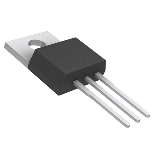
The IRL8113PBF is an N-Channel MOSFET manufactured by Infineon Technologies, rated for 30V drain-to-source voltage with 105A continuous drain current at 25°C. This device is housed in a TO-220AB through-hole package and is part of the HEXFET® series. The IRL8113PBF is classified as obsolete, making identification of equivalent and substitute parts essential for ongoing design support, production continuity, and system maintenance. Substitute parts must maintain electrical compatibility across voltage, current, and thermal specifications while accommodating the through-hole TO-220AB package format.
Substiute Parts
Key Parameters
| Parameter | Value | Unit |
|---|---|---|
| Drain to Source Voltage (Vdss) | 30 | V |
| Continuous Drain Current (Id) @ 25°C | 105 | A |
| On-State Resistance (Rds On Max) @ 10V | 6 | mOhm |
| Gate Threshold Voltage (Vgs(th) Max) | 2.25 | V |
| Power Dissipation (Max) | 110 | W |
| Operating Temperature Range | -55 to 175 | °C |
| Package Type | TO-220AB | Through Hole |
| FET Type | N-Channel | — |
| Technology | MOSFET (Metal Oxide) | — |
Substitute Part Grouping Explanation
Substitution eligibility for the IRL8113PBF is determined by the following critical parameters:
Voltage Rating: All substitute parts must maintain a Drain-to-Source Voltage (Vdss) rating of 30V or higher to ensure safe operation within the original design envelope.
Current Capacity: Substitute parts must support continuous drain current (Id) at 25°C equal to or exceeding 105A to maintain system performance and thermal margin.
On-State Resistance (Rds On): The maximum on-state resistance at 10V gate drive must not exceed 6 mOhm to preserve power efficiency and thermal characteristics.
Package Compatibility: All substitutes must use the TO-220AB through-hole package format to ensure mechanical and thermal interface compatibility with existing PCB layouts and heatsink assemblies.
Operating Temperature: Substitute parts must support the full operating temperature range of -55°C to 175°C (junction temperature).
Compliance Standards: All substitute parts must maintain RoHS3 compliance and REACH unaffected status to satisfy regulatory and supply chain requirements.
The following substitute parts meet these criteria and are grouped by manufacturer and product status.
Parameter Comparison
| Part Number | Manufacturer | Vdss (V) | Id @ 25°C (A) | Rds On Max @ 10V (mOhm) | Power Dissipation (W) | Package | Product Status |
|---|---|---|---|---|---|---|---|
| IRL8113PBF | Infineon Technologies | 30 | 105 | 6 | 110 | TO-220AB | Obsolete |
| IRLB8748PBF | Infineon Technologies | 30 | 92 | 4.8 | 75 | TO-220AB | Active |
| PSMN2R0-30PL,127 | Nexperia USA Inc. | 30 | 100 | 2.1 | 211 | TO-220AB | Obsolete |
| PSMN4R3-30PL,127 | Nexperia USA Inc. | 30 | 100 | 4.3 | 103 | TO-220AB | Obsolete |
| STP160N3LL | STMicroelectronics | 30 | 120 | 3.2 | 136 | TO-220 | Active |
| STP90NF03L | STMicroelectronics | 30 | 90 | 6.5 | 150 | TO-220 | Not For New Designs |
Engineering Selection Recommendations
Primary Recommendation: IRLB8748PBF
The IRLB8748PBF is an active product from Infineon Technologies with identical voltage rating (30V) and compatible package (TO-220AB). Although the continuous drain current is rated at 92A compared to the original 105A, the on-state resistance is superior at 4.8 mOhm versus 6 mOhm, resulting in lower power dissipation and improved thermal performance. This part is suitable for applications where the 92A rating meets system requirements. RoHS3 compliance and REACH unaffected status are confirmed.
Secondary Recommendation: STP160N3LL
The STP160N3LL from STMicroelectronics is an active product with superior current capacity (120A) and lower on-state resistance (3.2 mOhm). The 30V voltage rating matches the original specification. The package is TO-220 (compatible with TO-220AB mechanical footprint). Power dissipation capability is 136W, exceeding the original 110W. This part is recommended for applications requiring higher current margin or improved thermal performance. RoHS3 compliance and REACH unaffected status are confirmed.
Alternative Consideration: PSMN2R0-30PL,127
The PSMN2R0-30PL,127 from Nexperia USA Inc. provides the lowest on-state resistance (2.1 mOhm) and highest power dissipation rating (211W) among available substitutes. Current capacity is 100A at 25°C. The part is obsolete but remains available in inventory. This option is suitable for designs prioritizing thermal efficiency and power handling. RoHS3 compliance and REACH unaffected status are confirmed.
Not Recommended for New Designs: STP90NF03L
The STP90NF03L carries a product status of "Not For New Designs" and is therefore unsuitable for new development efforts, despite meeting electrical specifications.
Frequently Asked Questions (FAQ)
Q: Can the IRLB8748PBF replace the IRL8113PBF in all applications?
A: The IRLB8748PBF is electrically compatible with the IRL8113PBF for applications where the 92A continuous drain current rating is sufficient. Both devices share identical 30V voltage rating, TO-220AB package, and operating temperature range. The IRLB8748PBF exhibits superior on-state resistance (4.8 mOhm vs. 6 mOhm), resulting in lower power dissipation. System design must confirm that 92A meets application current requirements.
Q: What is the difference between TO-220AB and TO-220 packages?
A: Both TO-220AB and TO-220 are through-hole packages with identical lead spacing and mechanical footprint compatibility. The primary difference is in lead finish and plating specifications. Parts specified as TO-220 or TO-220AB are mechanically interchangeable on standard PCB layouts and heatsink assemblies.
Q: Why is the PSMN2R0-30PL,127 listed as obsolete if it performs better than the IRL8113PBF?
A: Product status reflects manufacturer production and support decisions, not performance capability. The PSMN2R0-30PL,127 is obsolete but remains available in inventory. Obsolete parts carry no guarantee of future availability or production support. For new designs, active products such as IRLB8748PBF or STP160N3LL are preferred to ensure long-term supply chain stability.
Q: Are all substitute parts RoHS3 compliant?
A: Yes. All substitute parts listed in this reference meet RoHS3 compliance and REACH unaffected status, matching the regulatory requirements of the original IRL8113PBF.
Q: What is the significance of on-state resistance (Rds On) in MOSFET selection?
A: On-state resistance directly determines power dissipation during conduction. Lower Rds On values reduce heat generation and improve efficiency. The IRL8113PBF specifies 6 mOhm maximum at 10V gate drive. Substitute parts with lower Rds On values (such as PSMN2R0-30PL,127 at 2.1 mOhm) provide thermal margin and improved system efficiency, while parts with higher Rds On values (such as STP90NF03L at 6.5 mOhm) approach the original specification.
Q: Can I use a 40V rated MOSFET as a substitute for a 30V rated device?
A: No. The IRL8113PBF is specified for 30V maximum drain-to-source voltage. Using a higher voltage rated device does not provide functional equivalence and introduces unnecessary cost and size penalties. All recommended substitutes maintain the 30V voltage rating to ensure design compatibility and cost optimization.
Q: What thermal considerations apply when selecting a substitute?
A: Power dissipation rating and on-state resistance determine thermal performance. The IRL8113PBF is rated for 110W maximum power dissipation. Substitute parts with higher power dissipation ratings (such as PSMN2R0-30PL,127 at 211W or STP160N3LL at 136W) provide additional thermal margin. Lower on-state resistance also reduces heat generation at equivalent current levels. Heatsink design and thermal interface material must be verified for the selected substitute to ensure junction temperature remains within the -55°C to 175°C operating range.
Alternative Parts

SJ6012L2TP
Littelfuse Inc.
6 Alternative Parts

JMK107BBJ476MA-RE
Taiyo Yuden
10 Alternative Parts

GMK107BBJ475MA-T
Taiyo Yuden
5 Alternative Parts
SJ6020N2ARP
Littelfuse Inc.
3 Alternative Parts
SJ6025R2ATP
Littelfuse Inc.
4 Alternative Parts

2474-05L
API Delevan Inc.
1 Alternative Parts

4590R-684K
API Delevan Inc.
1 Alternative Parts

CM6560R-334
API Delevan Inc.
1 Alternative Parts

CM6460-104
API Delevan Inc.
1 Alternative Parts

5526-12
API Delevan Inc.
1 Alternative Parts