


Request Quote
(Ships tomorrow)
IRL40B209 N-Channel MOSFET Equivalent & Substitute Parts
Part Overview
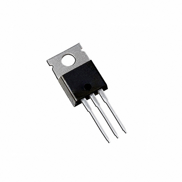
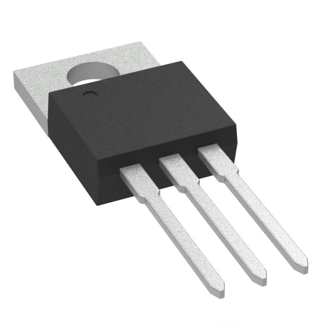
The IRL40B209 is an N-Channel MOSFET manufactured by Infineon Technologies, rated for 40V drain-to-source voltage with 195A continuous drain current at 25°C. This device is housed in a TO-220AB through-hole package and is part of the HEXFET® and StrongIRFET™ series. The IRL40B209 is classified as obsolete, making identification of functionally equivalent active alternatives essential for new designs and production continuity. Substitute parts must maintain electrical compatibility across voltage, current, and thermal specifications while meeting modern compliance requirements.
Substiute Parts
Key Parameters
| Parameter | Value | Unit |
|---|---|---|
| Drain-to-Source Voltage (Vdss) | 40 | V |
| Continuous Drain Current (Id) @ 25°C | 195 | A (Tc) |
| On-State Resistance (Rds On Max) @ 100A, 10V | 1.25 | mOhm |
| Gate Threshold Voltage (Vgs(th) Max) @ 250µA | 2.4 | V |
| Power Dissipation (Max) | 375 | W (Tc) |
| Operating Temperature Range | -55 to 175 | °C (TJ) |
| Package Type | TO-220AB | Through Hole |
| FET Technology | MOSFET (Metal Oxide) | N-Channel |
Substitute Part Grouping Explanation
Substitution eligibility for the IRL40B209 is determined by the following critical parameters:
Primary Compatibility Criteria:
- Drain-to-Source Voltage (Vdss): Substitute must equal or exceed 40V
- Continuous Drain Current (Id): Substitute must equal or exceed 195A at rated temperature
- On-State Resistance (Rds On): Substitute must not significantly exceed 1.25 mOhm to maintain thermal and efficiency performance
- Package Type: TO-220AB or equivalent TO-220-3 through-hole configuration
- FET Type: N-Channel MOSFET technology
- Operating Temperature Range: Must support -55°C to 175°C
Secondary Compatibility Criteria:
- Gate Threshold Voltage (Vgs(th)): Must remain within ±20V gate voltage specification
- Power Dissipation: Must support 375W thermal rating
- Compliance: RoHS3 compliance required for modern applications
The two qualified substitutes listed below meet these criteria with documented electrical equivalence and active product status.
Parameter Comparison
| Parameter | IRL40B209 | IRFB7430PBF | CSD18536KCS | Unit |
|---|---|---|---|---|
| Manufacturer | Infineon Technologies | Infineon Technologies | Texas Instruments | — |
| Product Status | Obsolete | Active | Active | — |
| Drain-to-Source Voltage (Vdss) | 40 | 40 | 60 | V |
| Continuous Drain Current (Id) @ 25°C | 195 (Tc) | 195 (Tc) | 200 (Ta) | A |
| Rds On (Max) @ 100A, 10V | 1.25 | 1.3 | 1.6 | mOhm |
| Gate Threshold Voltage (Vgs(th) Max) @ 250µA | 2.4 | 3.9 | 2.2 | V |
| Gate Charge (Qg Max) | 270 @ 4.5V | 460 @ 10V | 108 @ 10V | nC |
| Input Capacitance (Ciss Max) @ Vds | 15140 @ 25V | 14240 @ 25V | 11430 @ 30V | pF |
| Power Dissipation (Max) | 375 | 375 | 375 | W (Tc) |
| Operating Temperature Range | -55 to 175 | -55 to 175 | -55 to 175 | °C (TJ) |
| Package Type | TO-220AB | TO-220AB | TO-220-3 | — |
| RoHS Status | ROHS3 Compliant | ROHS3 Compliant | ROHS3 Compliant | — |
| Inventory Status | 2218 Pcs (Obsolete) | 43400 Pcs (Active) | 956 Pcs (Active) | — |
Engineering Selection Recommendations
IRFB7430PBF (Infineon Technologies) - Primary Substitute
The IRFB7430PBF is the manufacturer-recommended direct substitute for the IRL40B209. Both devices are manufactured by Infineon Technologies and share identical voltage (40V) and current (195A) ratings. The IRFB7430PBF maintains the same power dissipation (375W) and operating temperature range (-55°C to 175°C). This part is currently in active production with substantial inventory availability (43,400 units). The on-state resistance specification (1.3 mOhm @ 100A, 10V) is marginally higher than the original part (1.25 mOhm), representing a 4% increase that remains within acceptable thermal margins for most applications. The IRFB7430PBF carries ROHS3 compliance and is packaged in TO-220AB configuration, ensuring direct mechanical compatibility. This substitute is recommended for applications requiring minimal design modification and maximum electrical equivalence.
CSD18536KCS (Texas Instruments) - Alternative Substitute
The CSD18536KCS is a cross-manufacturer substitute from Texas Instruments, part of the NexFET™ series. This device exceeds the voltage specification of the IRL40B209 (60V vs. 40V), providing additional voltage margin for applications subject to transient overvoltage conditions. The continuous drain current rating (200A @ Ta) exceeds the original specification (195A @ Tc), and power dissipation remains at 375W. The on-state resistance (1.6 mOhm @ 100A, 10V) is higher than both the original part and the IRFB7430PBF, representing a 28% increase relative to the IRL40B209. The CSD18536KCS features significantly lower gate charge (108 nC @ 10V) compared to the IRL40B209 (270 nC @ 4.5V), which may reduce gate drive power requirements in high-frequency switching applications. This part is in active production with ROHS3 compliance. The CSD18536KCS is suitable for applications where higher voltage rating and lower gate charge are beneficial, though the increased on-state resistance may result in higher conduction losses.
Product Status Consideration
The IRL40B209 is classified as obsolete. Both substitute parts are in active production status, ensuring long-term availability and supply chain continuity. Selection between IRFB7430PBF and CSD18536KCS should be based on specific application requirements regarding voltage margin, gate drive characteristics, and acceptable conduction loss levels.
Frequently Asked Questions (FAQ)
Q: Can the IRFB7430PBF be used as a direct replacement for the IRL40B209 without circuit modification?
A: The IRFB7430PBF is electrically compatible with the IRL40B209 across all critical parameters: identical voltage rating (40V), current rating (195A), power dissipation (375W), and operating temperature range (-55°C to 175°C). Both devices use TO-220AB packaging. The primary difference is a 4% increase in on-state resistance (1.3 mOhm vs. 1.25 mOhm), which typically does not require circuit redesign. Gate threshold voltage differs (3.9V vs. 2.4V), which may affect gate drive timing but remains within the ±20V gate voltage specification. The IRFB7430PBF is the manufacturer-recommended substitute and is suitable for direct replacement in most applications.
Q: What are the advantages of using the CSD18536KCS over the IRFB7430PBF?
A: The CSD18536KCS offers two primary advantages: (1) higher voltage rating (60V vs. 40V), providing additional margin against transient overvoltage events, and (2) significantly lower gate charge (108 nC vs. 270 nC for the original part), which reduces gate drive power consumption and may enable faster switching transitions. The disadvantage is higher on-state resistance (1.6 mOhm), resulting in increased conduction losses. Selection depends on whether voltage margin and gate drive efficiency outweigh the cost of higher conduction losses in the specific application.
Q: Are there any package compatibility issues between these substitutes?
A: The IRL40B209 and IRFB7430PBF both use TO-220AB packaging, ensuring mechanical and thermal compatibility. The CSD18536KCS uses TO-220-3 packaging, which is mechanically equivalent to TO-220AB and compatible with standard TO-220 PCB footprints and heatsink mounting hardware. No package-related design modifications are required for any of these substitutes.
Q: Do all three parts meet current compliance requirements?
A: Yes. The IRL40B209, IRFB7430PBF, and CSD18536KCS are all ROHS3 compliant. The IRFB7430PBF and CSD18536KCS are in active production and carry current compliance certifications. The IRL40B209 is obsolete but was manufactured to ROHS3 standards. For new designs, the active substitutes (IRFB7430PBF or CSD18536KCS) are recommended to ensure long-term compliance and supply availability.
Q: How do the gate charge specifications affect circuit design?
A: Gate charge (Qg) determines the energy required to switch the MOSFET on and off. The IRL40B209 specifies 270 nC @ 4.5V, the IRFB7430PBF specifies 460 nC @ 10V, and the CSD18536KCS specifies 108 nC @ 10V. Higher gate charge requires more gate drive current or longer switching times. The CSD18536KCS has significantly lower gate charge, which may reduce gate driver power dissipation and enable faster switching in high-frequency applications. The IRFB7430PBF has higher gate charge, which may require gate driver adjustment in timing-critical circuits. Gate charge differences do not prevent substitution but should be evaluated in high-frequency or power-limited gate drive circuits.
Q: What is the significance of the on-state resistance (Rds On) differences?
A: On-state resistance directly affects conduction losses (P = I²R). The IRL40B209 specifies 1.25 mOhm, the IRFB7430PBF specifies 1.3 mOhm (4% higher), and the CSD18536KCS specifies 1.6 mOhm (28% higher). At 195A continuous current, the power dissipation difference between the IRL40B209 and IRFB7430PBF is approximately 1.2W, which is typically negligible. The difference between the IRL40B209 and CSD18536KCS is approximately 8.4W, which may require heatsink adjustment in thermally constrained applications. For most applications, the IRFB7430PBF is preferred due to minimal resistance increase. The CSD18536KCS is suitable when voltage margin or gate charge reduction justifies the higher conduction loss.
Alternative Parts

SJ6012L2TP
Littelfuse Inc.
6 Alternative Parts

JMK107BBJ476MA-RE
Taiyo Yuden
10 Alternative Parts

GMK107BBJ475MA-T
Taiyo Yuden
5 Alternative Parts
SJ6020N2ARP
Littelfuse Inc.
3 Alternative Parts
SJ6025R2ATP
Littelfuse Inc.
4 Alternative Parts

2474-05L
API Delevan Inc.
1 Alternative Parts

4590R-684K
API Delevan Inc.
1 Alternative Parts

CM6560R-334
API Delevan Inc.
1 Alternative Parts

CM6460-104
API Delevan Inc.
1 Alternative Parts

5526-12
API Delevan Inc.
1 Alternative Parts