


Request Quote
(Ships tomorrow)
IRL3103LPBF Equivalent & Substitute Parts
Part Overview
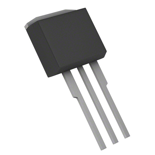
The IRL3103LPBF is an N-Channel MOSFET manufactured by Infineon Technologies, rated for 30V drain-to-source voltage with 64A continuous drain current at 25°C. This device is housed in a TO-262-3 Long Leads package and features the HEXFET® series technology. The part is classified as obsolete, making identification of suitable substitute components essential for ongoing design support, production continuity, and system maintenance applications.
Substiute Parts
Key Parameters
| Parameter | Value | Unit |
|---|---|---|
| Drain to Source Voltage (Vdss) | 30 | V |
| Continuous Drain Current (Id) @ 25°C | 64 | A |
| Rds On (Max) @ Id, Vgs | 12 mOhm @ 34A, 10V | mOhm |
| Gate Charge (Qg) (Max) @ Vgs | 33 | nC @ 4.5V |
| Power Dissipation (Max) | 94 | W |
| Operating Temperature Range | -55 to 175 | °C |
| Package Type | TO-262-3 | Through Hole |
| Vgs (Max) | ±16 | V |
| Input Capacitance (Ciss) @ Vds | 1650 pF @ 25V | pF |
Substitute Part Grouping Explanation
Substitution of the IRL3103LPBF is determined by the following critical electrical and mechanical parameters:
Electrical Compatibility Criteria:
- Drain-to-source voltage rating (Vdss) must equal or exceed 30V
- Continuous drain current (Id) must meet or exceed 64A at 25°C
- Gate-source voltage rating (Vgs) must accommodate ±16V operation
- On-state resistance (Rds On) must not significantly degrade circuit performance
- Operating temperature range must span -55°C to 175°C minimum
Mechanical Compatibility Criteria:
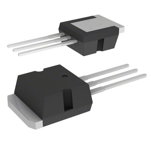
- Package type must be TO-262-3 Long Leads or equivalent I2PAK configuration
- Through-hole mounting requirement must be maintained
- Pin configuration must be compatible with existing PCB layouts
The STI55NF03L from STMicroelectronics meets the core substitution requirements based on matching voltage ratings, compatible current handling, and package compatibility, despite lower absolute current rating and power dissipation specifications.
Parameter Comparison
| Parameter | IRL3103LPBF (Infineon) | STI55NF03L (STMicroelectronics) | Compatibility Status |
|---|---|---|---|
| Drain to Source Voltage (Vdss) | 30 V | 30 V | Match |
| Continuous Drain Current (Id) @ 25°C | 64 A | 55 A | Substitute Lower |
| Rds On (Max) @ Vgs 10V | 12 mOhm @ 34A | 13 mOhm @ 27.5A | Comparable |
| Gate Charge (Qg) @ 4.5V | 33 nC | 27 nC | Substitute Lower |
| Power Dissipation (Max) | 94 W | 80 W | Substitute Lower |
| Operating Temperature Range | -55 to 175 °C | -60 to 175 °C | Substitute Wider |
| Vgs (Max) | ±16 V | ±16 V | Match |
| Input Capacitance (Ciss) @ 25V | 1650 pF | 1265 pF | Substitute Lower |
| Package Type | TO-262-3 | I2PAK / TO-262-3 | Compatible |
| Mounting Type | Through Hole | Through Hole | Match |
| Product Status | Obsolete | Obsolete | Both Obsolete |
Engineering Selection Recommendations
STI55NF03L as Primary Substitute:
The STI55NF03L qualifies as a functional substitute based on the following engineering criteria:
-
Voltage Rating Compatibility: Both devices share identical 30V Vdss ratings, ensuring direct voltage-level compatibility in circuit applications.
-
Gate Drive Compatibility: Matching ±16V Vgs (Max) specifications confirm gate-drive circuit compatibility without modification.
-
Package Compatibility: Both devices utilize TO-262-3 Long Leads configuration with I2PAK option, supporting direct PCB footprint compatibility.
-
Thermal Range: The STI55NF03L extends the lower operating temperature limit to -60°C, providing equivalent or superior thermal performance across the specified range.
-
Compliance Status: Both parts carry identical REACH Unaffected and EAR99 ECCN classifications, maintaining regulatory compliance equivalence.
Design Consideration: The STI55NF03L exhibits lower continuous drain current (55A versus 64A), reduced power dissipation (80W versus 94W), and lower gate charge (27nC versus 33nC). Circuit designs operating at or below 55A continuous current with thermal dissipation requirements under 80W will function without performance degradation. Applications requiring the full 64A rating or 94W dissipation capability must conduct thermal and current-path analysis to confirm suitability.
Frequently Asked Questions (FAQ)
Q: Can the STI55NF03L directly replace the IRL3103LPBF in all applications?
A: Direct replacement is possible for applications where continuous drain current does not exceed 55A and power dissipation remains below 80W. The matching voltage ratings (30V Vdss), gate-drive specifications (±16V Vgs), and package configuration (TO-262-3) support pin-for-pin compatibility. Applications requiring the full 64A rating or 94W dissipation must evaluate whether the substitute's lower specifications meet circuit requirements.
Q: What are the key electrical differences between these parts?
A: The primary differences are continuous drain current (64A versus 55A), power dissipation (94W versus 80W), gate charge (33nC versus 27nC), and input capacitance (1650pF versus 1265pF). The STI55NF03L's lower gate charge may reduce gate-drive power requirements. The lower input capacitance may improve switching speed characteristics. On-state resistance values are comparable (12mOhm versus 13mOhm).
Q: Are there package compatibility concerns?
A: Both devices use TO-262-3 Long Leads configuration with I2PAK option. The packages are mechanically and electrically compatible, supporting direct PCB footprint reuse without layout modification.
Q: What is the significance of both parts being obsolete?
A: Obsolete status indicates neither part is in active production. Both devices remain available through inventory channels. Long-term design strategies should consider identifying next-generation alternatives from current product lines for future production requirements.
Q: How should thermal design be evaluated for substitution?
A: The STI55NF03L's 80W maximum power dissipation is lower than the IRL3103LPBF's 94W rating. Thermal designs must verify that circuit operating conditions remain within the substitute's 80W limit. This includes evaluating junction temperature rise, heatsink requirements, and continuous current operation at 55A maximum.
Q: Are there gate-drive circuit modifications required?
A: No modifications are required. Both devices specify ±16V Vgs (Max) and support identical gate-drive voltage levels. The STI55NF03L's lower gate charge (27nC versus 33nC) may reduce gate-drive power consumption but does not require circuit changes.
Alternative Parts

SJ6012L2TP
Littelfuse Inc.
6 Alternative Parts

JMK107BBJ476MA-RE
Taiyo Yuden
10 Alternative Parts

GMK107BBJ475MA-T
Taiyo Yuden
5 Alternative Parts
SJ6020N2ARP
Littelfuse Inc.
3 Alternative Parts
SJ6025R2ATP
Littelfuse Inc.
4 Alternative Parts

2474-05L
API Delevan Inc.
1 Alternative Parts

4590R-684K
API Delevan Inc.
1 Alternative Parts

CM6560R-334
API Delevan Inc.
1 Alternative Parts

CM6460-104
API Delevan Inc.
1 Alternative Parts

5526-12
API Delevan Inc.
1 Alternative Parts