


Request Quote
(Ships tomorrow)
IRL2910L Equivalent & Substitute Parts
Part Overview
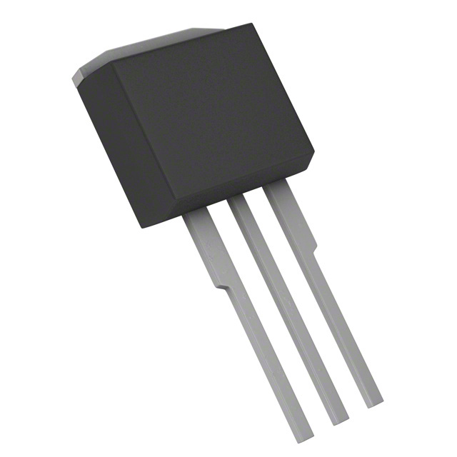
The IRL2910L is an N-Channel MOSFET manufactured by Infineon Technologies, rated for 100V drain-to-source voltage with 55A continuous drain current in a Through Hole TO-262 package. This device is classified as Obsolete, making identification of equivalent and substitute parts essential for ongoing system support and component procurement.
The obsolete status of the IRL2910L necessitates evaluation of alternative N-Channel MOSFETs that maintain electrical and mechanical compatibility within the same voltage and current class while meeting current manufacturing and compliance standards.
Substiute Parts
Key Parameters
| Parameter | Value | Unit |
|---|---|---|
| Drain to Source Voltage (Vdss) | 100 | V |
| Continuous Drain Current (Id) @ 25°C | 55 | A (Tc) |
| Rds On (Max) @ Id, Vgs | 26 mOhm @ 29A, 10V | mOhm |
| Gate Threshold Voltage Vgs(th) (Max) | 2 | V @ 250µA |
| Gate Charge (Qg) (Max) | 140 | nC @ 5V |
| Input Capacitance (Ciss) (Max) | 3700 | pF @ 25V |
| Power Dissipation (Max) | 200 | W (Tc) |
| Operating Temperature Range | -55 to 175 | °C (TJ) |
| Package Type | TO-262-3 | Through Hole |
| Mounting Type | Through Hole |
Substitute Part Grouping Explanation
Substitution of the IRL2910L is determined by strict alignment of the following electrical and mechanical parameters:
Critical Matching Parameters:
- Drain to Source Voltage (Vdss): 100V minimum
- Package Type: TO-262-3 Through Hole configuration
- FET Type: N-Channel MOSFET
- Technology: Metal Oxide Semiconductor
Functional Compatibility Parameters:
- Continuous Drain Current (Id): Must support circuit requirements
- On-State Resistance (Rds On): Must not exceed application thermal limits
- Gate Threshold Voltage (Vgs(th)): Must be compatible with drive circuitry
- Operating Temperature Range: Must encompass application environment
The IRF540ZLPBF qualifies as a substitute based on matching Vdss (100V), package configuration (TO-262-3), FET type (N-Channel), and technology (Metal Oxide). However, the continuous drain current rating differs (36A versus 55A), requiring application-level verification that circuit current demands do not exceed the substitute's rating.
Parameter Comparison
| Parameter | IRL2910L | IRF540ZLPBF | Unit |
|---|---|---|---|
| Manufacturer | Infineon Technologies | Infineon Technologies | |
| Drain to Source Voltage (Vdss) | 100 | 100 | V |
| Continuous Drain Current (Id) @ 25°C | 55 | 36 | A (Tc) |
| Rds On (Max) @ Vgs 10V | 26 mOhm @ 29A | 26.5 mOhm @ 22A | mOhm |
| Gate Threshold Voltage Vgs(th) (Max) | 2 | 4 | V @ 250µA |
| Gate Charge (Qg) (Max) | 140 | 63 | nC |
| Input Capacitance (Ciss) (Max) | 3700 | 1770 | pF @ 25V |
| Power Dissipation (Max) | 200 | 92 | W (Tc) |
| Operating Temperature Range | -55 to 175 | -55 to 175 | °C (TJ) |
| Package Type | TO-262-3 | TO-262-3 | |
| Mounting Type | Through Hole | Through Hole | |
| Product Status | Obsolete | Not For New Designs | |
| RoHS Status | RoHS non-compliant | ROHS3 Compliant |
Engineering Selection Recommendations
IRL2910L Status Consideration: The IRL2910L is classified as Obsolete. This status indicates the part is no longer manufactured and existing inventory is limited. Continued reliance on this part number for new procurement is not sustainable.
IRF540ZLPBF Evaluation: The IRF540ZLPBF carries a "Not For New Designs" status, indicating it remains available but is not recommended for new product development. However, it is ROHS3 Compliant, whereas the IRL2910L is RoHS non-compliant. Both devices share identical Vdss (100V), package configuration (TO-262-3), and operating temperature range (-55°C to 175°C).
Key Differences Affecting Selection:
- Continuous Drain Current: IRF540ZLPBF is rated at 36A versus IRL2910L at 55A. Applications requiring continuous drain currents exceeding 36A cannot use IRF540ZLPBF as a direct substitute.
- Power Dissipation: IRF540ZLPBF maximum power dissipation is 92W (Tc) versus 200W (Tc) for IRL2910L. Thermal design margins must be recalculated.
- Gate Threshold Voltage: IRF540ZLPBF Vgs(th) is 4V versus 2V for IRL2910L. Drive circuit voltage levels must be verified for compatibility.
- Gate Charge and Input Capacitance: IRF540ZLPBF exhibits lower values (63 nC and 1770 pF respectively), resulting in faster switching characteristics.
Compliance Consideration: IRF540ZLPBF compliance with ROHS3 standards provides regulatory advantage over the non-compliant IRL2910L for applications subject to environmental regulations.
Frequently Asked Questions (FAQ)
Q: Can IRF540ZLPBF directly replace IRL2910L in all applications?
A: No. While both devices share 100V Vdss rating and TO-262-3 package configuration, the IRF540ZLPBF continuous drain current rating of 36A is lower than the IRL2910L rating of 55A. Applications requiring continuous drain currents between 36A and 55A cannot use IRF540ZLPBF. Thermal design and power dissipation limits must also be re-evaluated, as IRF540ZLPBF maximum power dissipation is 92W (Tc) versus 200W (Tc) for IRL2910L.
Q: What are the key electrical differences between these parts?
A: Primary differences include: (1) Continuous Drain Current: IRL2910L 55A versus IRF540ZLPBF 36A; (2) Gate Threshold Voltage: IRL2910L 2V versus IRF540ZLPBF 4V; (3) Gate Charge: IRL2910L 140 nC versus IRF540ZLPBF 63 nC; (4) Input Capacitance: IRL2910L 3700 pF versus IRF540ZLPBF 1770 pF; (5) Power Dissipation: IRL2910L 200W (Tc) versus IRF540ZLPBF 92W (Tc).
Q: Are the packages mechanically identical?
A: Both devices use TO-262-3 Long Leads package configuration with Through Hole mounting. Mechanical compatibility is confirmed for PCB layout and thermal management considerations.
Q: What compliance differences exist?
A: IRL2910L is RoHS non-compliant. IRF540ZLPBF is ROHS3 Compliant. For applications subject to RoHS regulations, IRF540ZLPBF provides regulatory compliance advantage.
Q: How does gate threshold voltage difference affect circuit design?
A: IRL2910L gate threshold voltage is 2V versus IRF540ZLPBF at 4V. Drive circuits must supply sufficient gate voltage to turn on the selected device. The higher threshold voltage of IRF540ZLPBF may require adjustment of gate drive voltage levels or circuit timing.
Q: What impact do gate charge and input capacitance differences have?
A: IRF540ZLPBF exhibits lower gate charge (63 nC versus 140 nC) and lower input capacitance (1770 pF versus 3700 pF). This results in faster switching transitions and reduced gate drive power requirements, but may necessitate adjustment of gate drive circuit timing and impedance matching.
Q: Is IRF540ZLPBF suitable for new product designs?
A: IRF540ZLPBF carries "Not For New Designs" status. While it remains available for replacement and repair applications, it is not recommended as the primary component selection for new product development. Current-generation alternatives should be evaluated for new designs.
Alternative Parts

SJ6012L2TP
Littelfuse Inc.
6 Alternative Parts

JMK107BBJ476MA-RE
Taiyo Yuden
10 Alternative Parts

GMK107BBJ475MA-T
Taiyo Yuden
5 Alternative Parts
SJ6020N2ARP
Littelfuse Inc.
3 Alternative Parts
SJ6025R2ATP
Littelfuse Inc.
4 Alternative Parts

2474-05L
API Delevan Inc.
1 Alternative Parts

4590R-684K
API Delevan Inc.
1 Alternative Parts

CM6560R-334
API Delevan Inc.
1 Alternative Parts

CM6460-104
API Delevan Inc.
1 Alternative Parts

5526-12
API Delevan Inc.
1 Alternative Parts