


Request Quote
(Ships tomorrow)
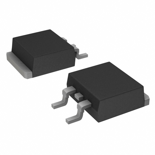
IRL1404ZS N-Channel 40V 75A MOSFET Equivalent & Substitute Parts
Part Overview
The IRL1404ZS is an N-Channel MOSFET manufactured by Infineon Technologies, rated for 40V drain-source voltage and 75A continuous drain current in a D2PAK surface mount package. This device belongs to the HEXFET® series and is classified as obsolete product status. Due to its obsolescence, identifying functionally equivalent substitute parts is essential for design continuity, production planning, and long-term supply chain management. Substitute parts must maintain compatibility across electrical ratings, thermal characteristics, and mechanical packaging to ensure direct replacement capability.
Substiute Parts
Key Parameters
| Parameter | IRL1404ZS Value | Unit |
|---|---|---|
| Drain-Source Voltage (Vdss) | 40 | V |
| Continuous Drain Current @ 25°C (Id) | 75 | A (Tc) |
| On-Resistance @ 75A, 10V (Rds On Max) | 3.1 | mOhm |
| Gate Threshold Voltage @ 250µA (Vgs(th) Max) | 2.7 | V |
| Gate Charge @ 5V (Qg Max) | 110 | nC |
| Input Capacitance @ 25V (Ciss Max) | 5080 | pF |
| Power Dissipation (Max) | 230 | W (Tc) |
| Operating Temperature Range | -55 to 175 | °C (TJ) |
| Package Type | D2PAK (TO-263-3) | Surface Mount |
| FET Type | N-Channel | — |
| Technology | MOSFET (Metal Oxide) | — |
Substitute Part Grouping Explanation
Substitute parts for the IRL1404ZS are selected based on strict electrical and mechanical compatibility criteria. The following parameters define acceptable substitution:
Primary Matching Criteria:
- Drain-Source Voltage (Vdss): Must equal or exceed 40V
- Package Type: Must be D2PAK or TO-263 variant (surface mount, 3-lead configuration with tab)
- FET Type: N-Channel only
- Technology: MOSFET (Metal Oxide)
- Operating Temperature Range: Must support -55°C to 175°C minimum
Secondary Compatibility Parameters:
- Continuous Drain Current (Id): Substitute must support minimum 75A at 25°C
- On-Resistance (Rds On): Lower or equal values indicate improved performance
- Gate Charge (Qg): Values within ±50% of original support equivalent switching characteristics
- Input Capacitance (Ciss): Values within ±50% of original maintain gate drive compatibility
- Power Dissipation: Substitute must support minimum 230W thermal rating
Substitutes are grouped by electrical performance tier:
- Tier 1 (Direct Replacement): Drain current 75–85A, Rds On 3.1–4.0 mOhm
- Tier 2 (Higher Performance): Drain current 80–110A, Rds On 2.5–3.5 mOhm
- Tier 3 (High Current): Drain current >150A, Rds On <3.0 mOhm
All substitute parts maintain D2PAK/TO-263 packaging and support the full -55°C to 175°C operating range.
Parameter Comparison
| Parameter | IRL1404ZS (Infineon) | STB120N4LF6 (STMicroelectronics) | 2SK3943-ZP-E1-AY (Renesas) | AOB240L (Alpha & Omega) | IXTA220N04T2-7 (IXYS) | SQM100N04-2M7_GE3 (Vishay) | STB270N4F3 (STMicroelectronics) |
|---|---|---|---|---|---|---|---|
| Vdss (V) | 40 | 40 | 40 | 40 | 40 | 40 | 40 |
| Id @ 25°C (A) | 75 | 80 | 82 | 105 (Tc) | 220 | 100 | 160 |
| Rds On Max (mOhm) | 3.1 @ 75A, 10V | 4.0 @ 40A, 10V | 3.5 @ 41A, 10V | 2.6 @ 20A, 10V | 3.5 @ 50A, 10V | 2.7 @ 30A, 10V | 2.5 @ 80A, 10V |
| Vgs(th) Max (V) | 2.7 @ 250µA | 3.0 @ 250µA | — | 2.2 @ 250µA | 4.0 @ 250µA | 3.5 @ 250µA | 4.0 @ 250µA |
| Qg Max (nC) | 110 @ 5V | 80 @ 10V | 93 @ 10V | 72 @ 10V | 112 @ 10V | 145 @ 10V | 150 @ 10V |
| Ciss Max (pF) | 5080 @ 25V | 4300 @ 25V | 5800 @ 10V | 3510 @ 20V | 6820 @ 25V | 7910 @ 25V | 7400 @ 25V |
| Power Dissipation Max (W) | 230 (Tc) | 110 (Tc) | 104 (Tc) | 176 (Tc) | 360 (Tc) | 157 (Tc) | 330 (Tc) |
| Operating Temp Range (°C) | -55 to 175 | -55 to 175 | to 150 | -55 to 175 | -55 to 175 | -55 to 175 | -55 to 175 |
| Package | D2PAK (TO-263-3) | TO-263 (D2PAK) | TO-263 | TO-263 (D2PAK) | TO-263-7 (IXTA) | TO-263 (D2PAK) | D2PAK (TO-263-3) |
| Product Status | Obsolete | Active | Active | Not For New Designs | Active | Active | Active |
| RoHS Compliance | Non-compliant | ROHS3 Compliant | ROHS3 Compliant | ROHS3 Compliant | ROHS3 Compliant | ROHS3 Compliant | ROHS3 Compliant |
| Automotive Grade | — | AEC-Q101 | — | — | — | AEC-Q101 | AEC-Q101 |
Engineering Selection Recommendations
Tier 1 Direct Replacement (75–85A Current Range):
STB120N4LF6 (STMicroelectronics) is the primary direct substitute. It provides 80A continuous drain current, matching the IRL1404ZS current requirement with 4.0 mOhm on-resistance. This part carries Active product status, ROHS3 compliance, and AEC-Q101 automotive qualification. Operating temperature range extends to 175°C, maintaining full compatibility. Gate charge of 80 nC at 10V is lower than the original, reducing gate drive power requirements. This part is recommended for applications requiring minimal design modification.
Tier 2 Higher Performance Substitutes (80–110A Current Range):
2SK3943-ZP-E1-AY (Renesas Electronics) delivers 82A continuous current with 3.5 mOhm on-resistance and 93 nC gate charge. Active product status and ROHS3 compliance are confirmed. However, maximum operating temperature is limited to 150°C, which is 25°C below the IRL1404ZS specification. This part is suitable only for applications with operating temperature ceiling below 150°C.
SQM100N04-2M7_GE3 (Vishay Siliconix) provides 100A continuous current with superior 2.7 mOhm on-resistance, reducing conduction losses. Active product status, ROHS3 compliance, and AEC-Q101 automotive qualification are confirmed. Input capacitance of 7910 pF exceeds the original by approximately 56%, requiring gate drive circuit verification. This part is suitable for applications where lower on-resistance and improved thermal performance justify increased gate capacitance.
Tier 3 High Current Substitutes (>150A Current Range):
STB270N4F3 (STMicroelectronics) provides 160A continuous current with 2.5 mOhm on-resistance and 330W power dissipation. Active product status, ROHS3 compliance, and AEC-Q101 automotive qualification are confirmed. Gate charge of 150 nC at 10V exceeds the original by 36%, requiring gate drive circuit re-evaluation. This part is suitable for applications requiring higher current capacity and improved thermal performance.
IXTA220N04T2-7 (IXYS) delivers 220A continuous current with 3.5 mOhm on-resistance and 360W power dissipation. Active product status and ROHS3 compliance are confirmed. Package variant is TO-263-7 (IXTA), which differs from standard D2PAK in lead configuration (6 leads + tab versus 2 leads + tab). This part requires PCB layout modification and is suitable only for applications where the alternative package is acceptable.
AOB240L (Alpha & Omega Semiconductor) Status:
AOB240L is classified as "Not For New Designs" and carries 105A continuous current with 2.6 mOhm on-resistance. Although electrically capable, this product status designation indicates manufacturer discontinuation trajectory. Use is not recommended for new designs or long-term production commitments.
Compliance and Certification Summary:
All recommended active substitutes (STB120N4LF6, SQM100N04-2M7_GE3, STB270N4F3) carry ROHS3 compliance, addressing the non-compliant status of the obsolete IRL1404ZS. STB120N4LF6 and SQM100N04-2M7_GE3 hold AEC-Q101 automotive qualification, supporting applications requiring automotive-grade component certification.
Frequently Asked Questions (FAQ)
Q1: Can STB120N4LF6 directly replace IRL1404ZS without circuit modification?
A: STB120N4LF6 is electrically compatible as a direct substitute. Both parts share 40V Vdss rating, D2PAK packaging, and support -55°C to 175°C operating range. The 80A continuous current of STB120N4LF6 exceeds the 75A requirement. Gate charge is lower (80 nC versus 110 nC), which reduces gate drive power but does not prevent direct substitution. PCB layout and thermal management remain unchanged. No circuit modification is required for basic functionality, though gate drive optimization may improve performance.
Q2: Why does IXTA220N04T2-7 have a different package designation (TO-263-7) compared to other substitutes?
A: IXTA220N04T2-7 uses TO-263-7 (IXTA variant) packaging with 6 leads plus tab, whereas IRL1404ZS and most substitutes use standard D2PAK (TO-263-3) with 2 leads plus tab. The additional leads in the IXTA package provide alternative connection points for improved thermal and electrical performance in high-current applications. Direct PCB substitution is not possible without layout redesign. This part is suitable only when the alternative package footprint can be accommodated.
Q3: What is the significance of the "Not For New Designs" status on AOB240L?
A: "Not For New Designs" indicates that the manufacturer (Alpha & Omega Semiconductor) has designated this part for end-of-life phase-out. While currently in stock (10,326 pcs), the manufacturer does not recommend this part for new product development. For existing designs already using AOB240L, continued supply may be available during a transition period. For new designs, selection of active-status parts (STB120N4LF6, SQM100N04-2M7_GE3, STB270N4F3) ensures long-term availability and manufacturer support.
Q4: How do gate charge differences affect circuit design when substituting parts?
A: Gate charge (Qg) determines the total charge required to switch the MOSFET from off to on state. IRL1404ZS specifies 110 nC at 5V. STB120N4LF6 specifies 80 nC at 10V (lower charge requirement), while STB270N4F3 specifies 150 nC at 10V (higher charge requirement). Lower gate charge reduces gate drive power dissipation and switching losses, improving efficiency. Higher gate charge increases gate drive circuit current demand and switching time. For direct substitution with minimal circuit change, parts with gate charge within ±50% of the original (55–165 nC range) are preferred. Parts outside this range may require gate drive circuit re-evaluation.
Q5: What does AEC-Q101 automotive qualification mean for component selection?
A: AEC-Q101 is an automotive industry standard qualification for discrete semiconductors, including MOSFETs. It certifies that the component meets stringent reliability, temperature cycling, and stress testing requirements specified by automotive manufacturers. Parts carrying AEC-Q101 qualification (STB120N4LF6, SQM100N04-2M7_GE3, STB270N4F3) are approved for automotive applications. The original IRL1404ZS does not carry this certification. For automotive applications, selection of AEC-Q101 qualified substitutes is mandatory.
Q6: Why is operating temperature range important when selecting a substitute?
A: Operating temperature range defines the thermal limits within which the MOSFET maintains specified electrical characteristics. IRL1404ZS supports -55°C to 175°C. Most substitutes match this range, ensuring compatibility across the full temperature spectrum. However, 2SK3943-ZP-E1-AY is limited to 150°C maximum, which is 25°C below the original specification. If the application requires operation above 150°C, this part is unsuitable. For applications with maximum operating temperature below 150°C, this limitation does not affect functionality.
Q7: How does on-resistance (Rds On) affect power dissipation and thermal management?
A: On-resistance determines conduction losses when the MOSFET conducts current. Power dissipation equals I²R, where I is drain current and R is on-resistance. IRL1404ZS specifies 3.1 mOhm at 75A, 10V. Lower on-resistance reduces conduction losses and heat generation. STB270N4F3 (2.5 mOhm) and SQM100N04-2M7_GE3 (2.7 mOhm) provide lower on-resistance, reducing thermal load. STB120N4LF6 (4.0 mOhm) has slightly higher on-resistance, increasing heat generation. For thermal-limited applications, lower on-resistance substitutes improve performance. For applications with adequate thermal management, on-resistance differences are secondary to current rating compatibility.
Q8: Can parts with higher continuous current ratings (e.g., STB270N4F3 at 160A) be used in place of the 75A IRL1404ZS?
A: Yes. Higher current-rated parts are electrically compatible substitutes. A 160A-rated MOSFET can safely conduct 75A without exceeding its design limits. The advantage is improved thermal margin and lower on-resistance, reducing power dissipation. The disadvantage is increased input capacitance (7400 pF versus 5080 pF), which may require gate drive circuit adjustment. Higher current-rated parts are typically larger dies with higher cost. Use higher current-rated substitutes only when improved thermal performance or lower on-resistance is required by the application.
Q9: What is the difference between Tc (case temperature) and Ta (ambient temperature) ratings?
A: Tc (case temperature) is the temperature measured at the device case or tab, typically under controlled thermal conditions. Ta (ambient temperature) is the surrounding air temperature. Manufacturers specify continuous current ratings at both Tc and Ta to account for different thermal management scenarios. IRL1404ZS specifies 75A at Tc (case temperature). AOB240L specifies 20A at Ta (ambient) and 105A at Tc (case). The Tc rating is higher because the case is cooler than the junction when proper thermal management is applied. When comparing current ratings, ensure both parts use the same temperature reference (Tc or Ta) for accurate comparison.
Q10: Are all D2PAK and TO-263 packages mechanically identical for PCB substitution?
A: Standard D2PAK (TO-263-3) and TO-263 packages are mechanically identical, with 2 leads plus tab in the same footprint. However, IXTA220N04T2-7 uses TO-263-7 (IXTA variant) with 6 leads plus tab, which has a different footprint and is not mechanically compatible without PCB redesign. When selecting substitutes, verify that the package designation matches the original (D2PAK or TO-263-3) to ensure direct PCB compatibility. Variant packages (TO-263-7, TO-263AB) may have different lead configurations and require layout modification.
Alternative Parts

SJ6012L2TP
Littelfuse Inc.
6 Alternative Parts

JMK107BBJ476MA-RE
Taiyo Yuden
10 Alternative Parts

GMK107BBJ475MA-T
Taiyo Yuden
5 Alternative Parts
SJ6020N2ARP
Littelfuse Inc.
3 Alternative Parts
SJ6025R2ATP
Littelfuse Inc.
4 Alternative Parts

2474-05L
API Delevan Inc.
1 Alternative Parts

4590R-684K
API Delevan Inc.
1 Alternative Parts

CM6560R-334
API Delevan Inc.
1 Alternative Parts

CM6460-104
API Delevan Inc.
1 Alternative Parts

5526-12
API Delevan Inc.
1 Alternative Parts