


Request Quote
(Ships tomorrow)
IRKT42/14A SCR Dual Thyristor Module - Equivalent & Substitute Parts
Part Overview
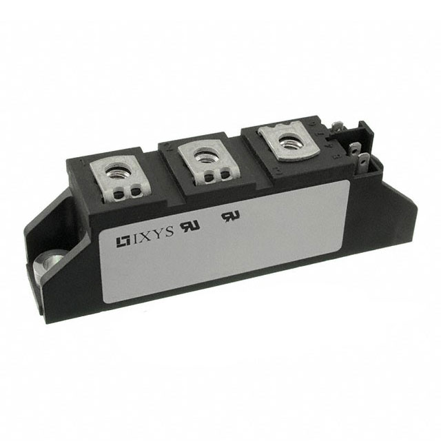
The IRKT42/14A is a dual SCR thyristor module manufactured by Vishay General Semiconductor - Diodes Division, rated for 1.4 kV off-state voltage with 100 A RMS on-state current capacity. This component is classified as obsolete, making equivalent substitute parts necessary for new designs and ongoing production requirements. The module features series-connected SCRs in ADD-A-PAK (3 + 4) chassis mount packaging, designed for high-voltage switching applications requiring dual thyristor functionality.
Substiute Parts
Key Parameters
| Parameter | Value |
|---|---|
| Manufacturer Part Number | IRKT42/14A |
| Manufacturer | Vishay General Semiconductor - Diodes Division |
| Category | Thyristors |
| Product Status | Obsolete |
| Structure | Series Connection - All SCRs |
| Number of SCRs | 2 |
| Voltage - Off State | 1.4 kV |
| Current - On State (It (AV)) (Max) | 45 A |
| Current - On State (It (RMS)) (Max) | 100 A |
| Voltage - Gate Trigger (Vgt) (Max) | 2.5 V |
| Current - Gate Trigger (Igt) (Max) | 150 mA |
| Current - Non Rep. Surge 50, 60Hz (Itsm) | 850 A, 890 A |
| Current - Hold (Ih) (Max) | 200 mA |
| Operating Temperature | -40°C ~ 125°C (TJ) |
| Mounting Type | Chassis Mount |
| Package / Case | ADD-A-PAK (3 + 4) |
| RoHS Status | RoHS non-compliant |
| REACH Status | REACH Unaffected |
Substitute Part Grouping Explanation
Substitution eligibility for the IRKT42/14A is determined by the following critical parameters:
- Voltage - Off State: 1.4 kV (exact match required)
- Structure: Series Connection - All SCRs (exact match required)
- Number of SCRs: 2 (exact match required)
- Mounting Type: Chassis Mount (exact match required)
- Operating Temperature Range: -40°C ~ 125°C (exact match required)
The three substitute parts (MCC26-14IO1B, MCC72-14IO1B, MCC95-14IO1B) all meet these core electrical and mechanical requirements. However, they differ in on-state current ratings and package configuration. The MCC26-14IO1B provides lower current capacity (50 A RMS), while MCC72-14IO1B and MCC95-14IO1B both support higher current capacity (180 A RMS). All substitutes use TO-240AA packaging instead of the original ADD-A-PAK configuration and feature active product status with RoHS3 compliance.
Parameter Comparison
| Parameter | IRKT42/14A | MCC26-14IO1B | MCC72-14IO1B | MCC95-14IO1B |
|---|---|---|---|---|
| Manufacturer | Vishay | IXYS | IXYS | IXYS |
| Product Status | Obsolete | Active | Active | Active |
| Voltage - Off State | 1.4 kV | 1.4 kV | 1.4 kV | 1.4 kV |
| Current - On State (It (AV)) (Max) | 45 A | 32 A | 115 A | 116 A |
| Current - On State (It (RMS)) (Max) | 100 A | 50 A | 180 A | 180 A |
| Voltage - Gate Trigger (Vgt) (Max) | 2.5 V | 1.5 V | 2.5 V | 2.5 V |
| Current - Gate Trigger (Igt) (Max) | 150 mA | 100 mA | 150 mA | 150 mA |
| Current - Non Rep. Surge 50, 60Hz (Itsm) | 850 A, 890 A | 520 A, 560 A | 1700 A, 1800 A | 2250 A, 2400 A |
| Current - Hold (Ih) (Max) | 200 mA | 200 mA | 200 mA | 200 mA |
| Operating Temperature | -40°C ~ 125°C | -40°C ~ 125°C | -40°C ~ 125°C | -40°C ~ 125°C |
| Mounting Type | Chassis Mount | Chassis Mount | Chassis Mount | Chassis Mount |
| Package / Case | ADD-A-PAK (3 + 4) | TO-240AA | TO-240AA | TO-240AA |
| RoHS Status | RoHS non-compliant | RoHS3 Compliant | RoHS3 Compliant | RoHS3 Compliant |
| REACH Status | REACH Unaffected | REACH Unaffected | REACH Unaffected | REACH Unaffected |
Engineering Selection Recommendations
Selection among the three substitute parts depends on application current requirements and regulatory compliance needs:
MCC26-14IO1B is suitable for applications requiring lower on-state current capacity (50 A RMS maximum). This part provides the most conservative current rating and is appropriate for designs where the IRKT42/14A's 100 A RMS capacity exceeds system requirements.
MCC72-14IO1B and MCC95-14IO1B both support 180 A RMS on-state current, exceeding the IRKT42/14A specification. MCC72-14IO1B provides 1700 A / 1800 A non-repetitive surge current, while MCC95-14IO1B provides 2250 A / 2400 A non-repetitive surge current. Both are suitable for applications requiring higher current capacity than the original part.
All three substitute parts carry active product status and RoHS3 compliance, addressing the obsolescence of the IRKT42/14A. The transition from ADD-A-PAK to TO-240AA packaging requires mechanical redesign of the mounting interface. Gate trigger voltage differs for MCC26-14IO1B (1.5 V maximum) compared to the original specification (2.5 V maximum), requiring gate drive circuit verification.
Frequently Asked Questions (FAQ)
Q: Can MCC26-14IO1B directly replace IRKT42/14A in all applications?
A: MCC26-14IO1B meets the core electrical parameters (1.4 kV off-state voltage, series-connected dual SCRs, -40°C to 125°C operating range) but provides lower on-state current capacity (50 A RMS versus 100 A RMS). Substitution is valid only if application current requirements do not exceed 50 A RMS. The lower gate trigger voltage (1.5 V versus 2.5 V) requires gate drive circuit evaluation.
Q: What are the differences between MCC72-14IO1B and MCC95-14IO1B?
A: Both parts provide identical on-state current ratings (180 A RMS) and gate trigger specifications (2.5 V maximum, 150 mA maximum). The primary difference is non-repetitive surge current capacity: MCC72-14IO1B supports 1700 A / 1800 A, while MCC95-14IO1B supports 2250 A / 2400 A. Selection depends on application surge current requirements.
Q: Does the package change from ADD-A-PAK to TO-240AA affect electrical performance?
A: The package change is mechanical only. Both ADD-A-PAK and TO-240AA are chassis mount configurations with identical electrical characteristics for the specified parameters. Mechanical redesign of the mounting interface is required.
Q: Are all substitute parts RoHS compliant?
A: Yes. MCC26-14IO1B, MCC72-14IO1B, and MCC95-14IO1B are all RoHS3 compliant, addressing regulatory requirements that the obsolete IRKT42/14A (RoHS non-compliant) does not meet.
Q: What is the impact of the gate trigger voltage difference in MCC26-14IO1B?
A: MCC26-14IO1B specifies 1.5 V maximum gate trigger voltage compared to 2.5 V for the IRKT42/14A. This lower threshold requires verification that existing gate drive circuits provide sufficient voltage margin and current capacity (100 mA maximum for MCC26-14IO1B versus 150 mA for the original part).
Alternative Parts

SJ6012L2TP
Littelfuse Inc.
6 Alternative Parts

JMK107BBJ476MA-RE
Taiyo Yuden
10 Alternative Parts

GMK107BBJ475MA-T
Taiyo Yuden
5 Alternative Parts
SJ6020N2ARP
Littelfuse Inc.
3 Alternative Parts
SJ6025R2ATP
Littelfuse Inc.
4 Alternative Parts

2474-05L
API Delevan Inc.
1 Alternative Parts

4590R-684K
API Delevan Inc.
1 Alternative Parts

CM6560R-334
API Delevan Inc.
1 Alternative Parts

CM6460-104
API Delevan Inc.
1 Alternative Parts

5526-12
API Delevan Inc.
1 Alternative Parts