


Request Quote
(Ships tomorrow)
IRGP4650DPBF IGBT Equivalent & Substitute Parts
Part Overview
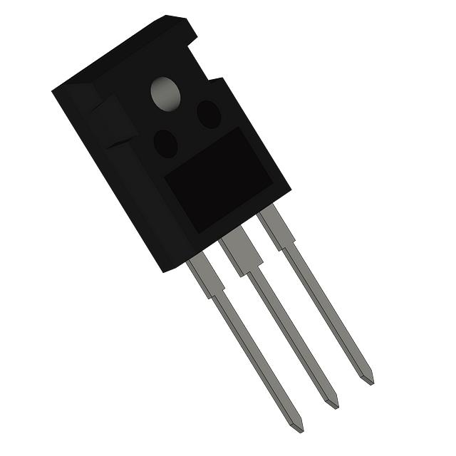
The IRGP4650DPBF is a 600V, 76A IGBT manufactured by Infineon Technologies in TO-247AC package configuration. This device is classified as obsolete, necessitating identification of functionally equivalent alternatives for ongoing design support and procurement continuity. The part operates at maximum junction temperatures from -55°C to 175°C and delivers 268W power dissipation capability. Substitute parts must maintain electrical compatibility across voltage, current, and thermal operating ranges while accommodating mechanical package variations.
Substiute Parts
Key Parameters
| Parameter | Value | Unit |
|---|---|---|
| Voltage - Collector Emitter Breakdown (Max) | 600 | V |
| Current - Collector (Ic) (Max) | 76 | A |
| Current - Collector Pulsed (Icm) | 105 | A |
| Power - Max | 268 | W |
| Vce(on) (Max) @ Vge, Ic | 1.9V @ 15V, 35A | V |
| Gate Charge | 104 | nC |
| Switching Energy (on/off) | 390µJ / 632µJ | µJ |
| Td (on/off) @ 25°C | 46ns / 105ns | ns |
| Operating Temperature Range | -55 to 175 | °C |
| Package / Case | TO-247-3 | — |
| Mounting Type | Through Hole | — |
| RoHS Status | ROHS3 Compliant | — |
Substitute Part Grouping Explanation
Substitution eligibility is determined by the following criteria applied strictly to provided parameters:
Primary Compatibility Criteria:
- Voltage - Collector Emitter Breakdown (Max): 600V or higher
- Current - Collector (Ic) (Max): 76A or higher
- Package / Case: TO-247-3 or mechanically compatible variant
- Mounting Type: Through Hole
- Operating Temperature Range: Must encompass -55°C to 175°C or equivalent upper limit
Secondary Compatibility Criteria:
- Power dissipation capability: 268W or higher preferred
- Vce(on) characteristics: Lower or equivalent values indicate improved performance
- Gate Charge: Values within ±50% of original support similar drive circuit requirements
- Switching Energy: Comparable values ensure circuit timing compatibility
Substitute parts are grouped into two categories: Manufacturer Recommended (direct Infineon alternatives and cross-manufacturer selections) and Direct Alternatives (functionally equivalent parts from other manufacturers meeting all primary criteria).
Parameter Comparison
| Part Number | Manufacturer | Vce(br) Max (V) | Ic Max (A) | Icm (A) | Power Max (W) | Vce(on) @ Test (V) | Gate Charge (nC) | Package | Status |
|---|---|---|---|---|---|---|---|---|---|
| IRGP4650DPBF | Infineon | 600 | 76 | 105 | 268 | 1.9 @ 15V, 35A | 104 | TO-247-3 | Obsolete |
| IKW50N60DTPXKSA1 | Infineon | 600 | 80 | 150 | 319.2 | 1.8 @ 15V, 50A | 249 | PG-TO247-3 | Not For New Designs |
| STGW60H65DFB | STMicroelectronics | 650 | 80 | 240 | 375 | 2.0 @ 15V, 60A | 306 | TO-247-3 | Active |
| FGH50N6S2D | Fairchild Semiconductor | 600 | 75 | 240 | 463 | 2.7 @ 15V, 30A | 70 | TO-247-3 | Active |
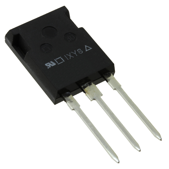
| IXGH28N60B3D1 | IXYS | 600 | 66 | 150 | 190 | 1.8 @ 15V, 24A | 62 | TO-247-3 | Active |
| IXGH48N60C3D1 | IXYS | 600 | 75 | 250 | 300 | 2.5 @ 15V, 30A | 77 | TO-247-3 | Active |
| IXGH60N60C3D1 | IXYS | 600 | 75 | 300 | 380 | 2.5 @ 15V, 40A | 115 | TO-247-3 | Active |
| IXGH64N60B3 | IXYS | 600 | — | 400 | 460 | 1.8 @ 15V, 50A | 168 | TO-247-3 | Active |
| IXGH72N60A3 | IXYS | 600 | 75 | 400 | 540 | 1.35 @ 15V, 60A | 230 | TO-247-3 | Active |
| IXGH90N60B3 | IXYS | 600 | 75 | 500 | 660 | 1.8 @ 15V, 90A | 172 | TO-247-3 | Active |
| IXGK50N60B2D1 | IXYS | 600 | 75 | 200 | 400 | 2.0 @ 15V, 40A | 140 | TO-264-3 | Active |
Engineering Selection Recommendations
Tier 1 - Direct Replacement (Highest Compatibility):
STGW60H65DFB (STMicroelectronics) meets all primary criteria with active product status. Voltage rating of 650V exceeds the 600V requirement, providing additional design margin. Current rating of 80A accommodates the 76A specification. TO-247-3 package maintains mechanical compatibility. RoHS3 compliance and REACH unaffected status align with regulatory requirements. Power dissipation of 375W exceeds the 268W baseline.
Tier 2 - Functional Equivalents (Infineon Alternatives):
IKW50N60DTPXKSA1 (Infineon TrenchStop™ series) provides 80A current capability and 319.2W power rating. PG-TO247-3 package is mechanically compatible with TO-247-3. Product status is "Not For New Designs," indicating limited long-term availability. Gate charge of 249nC requires verification of gate drive circuit compatibility compared to the original 104nC specification.
Tier 3 - Cross-Manufacturer Alternatives (Active Status):
IXYS GenX3™ series devices (IXGH48N60C3D1, IXGH60N60C3D1, IXGH72N60A3, IXGH90N60B3) provide current ratings of 75A or higher with TO-247-3 package compatibility. All devices maintain 600V voltage rating and active product status. Power dissipation ranges from 300W to 660W, exceeding the 268W requirement. Gate charge values range from 77nC to 230nC; higher values require gate drive circuit assessment.
Tier 4 - Alternative Package Consideration:
IXGK50N60B2D1 (IXYS HiPerFAST™ series) offers TO-264-3 package, which differs mechanically from TO-247-3. This option is suitable only when PCB layout and thermal management accommodate the alternative package footprint.
Compliance Verification:
All recommended substitutes maintain RoHS3 compliance and REACH unaffected status, consistent with the original IRGP4650DPBF specifications. Operating temperature ranges of -55°C to 150°C (IXYS devices) or -55°C to 175°C (STMicroelectronics, Fairchild) satisfy the original -55°C to 175°C requirement.
Frequently Asked Questions (FAQ)
Q1: Can IXGH72N60A3 directly replace IRGP4650DPBF without circuit modifications?
A: IXGH72N60A3 meets voltage (600V), current (75A), and package (TO-247-3) requirements. However, gate charge increases from 104nC to 230nC. Gate drive circuits must be verified to supply adequate charge within acceptable switching time windows. Switching energy characteristics differ significantly (1.38mJ on-state vs. 390µJ original), requiring thermal analysis of the application.
Q2: What is the significance of the TO-247-3 versus TO-247AD package designation?
A: Both designations refer to the same physical TO-247-3 package footprint and pin configuration. TO-247AD is a supplier-specific designation used by IXYS. Mechanical and electrical compatibility is maintained. PCB layouts designed for TO-247-3 accommodate both designations without modification.
Q3: Why does STGW60H65DFB have a 650V rating when the original is 600V?
A: The 650V rating provides additional voltage margin for transient overvoltage conditions common in switching applications. This higher rating does not compromise performance in 600V circuits and enhances reliability. The device remains fully compatible with 600V system designs.
Q4: Is IXGK50N60B2D1 suitable as a substitute despite the TO-264 package difference?
A: IXGK50N60B2D1 meets electrical specifications but requires PCB redesign due to TO-264-3 package footprint differences from TO-247-3. This option is viable only when layout modifications are acceptable. Thermal management characteristics may differ due to package geometry variations.
Q5: How do switching energy differences affect circuit performance?
A: Switching energy (on-state and off-state) determines power dissipation during transitions. Higher switching energy increases thermal load and may require enhanced heat sinking. Lower switching energy reduces EMI and improves efficiency. Application-specific thermal analysis is necessary when substituting parts with significantly different switching energy values.
Q6: What does "Not For New Designs" status mean for IKW50N60DTPXKSA1?
A: This status indicates the manufacturer is not recommending the part for new circuit designs, though existing inventory remains available. Long-term supply continuity is not guaranteed. For new designs, active-status alternatives such as STGW60H65DFB or IXYS GenX3™ series are preferred.
Q7: Are all substitute parts RoHS3 compliant?
A: All recommended substitutes listed maintain RoHS3 compliance and REACH unaffected status, consistent with the original IRGP4650DPBF. Compliance documentation should be verified with the specific supplier for procurement batches.
Q8: How does gate charge affect gate drive circuit design?
A: Gate charge (Qg) determines the total charge required to switch the IGBT fully on or off. Higher gate charge requires larger gate drive current or longer switching times. Original IRGP4650DPBF specifies 104nC. Substitutes range from 62nC to 306nC. Gate drive circuits must supply sufficient current to achieve desired switching speeds without exceeding maximum gate voltage ratings (typically 15V to 20V).
Alternative Parts

SJ6012L2TP
Littelfuse Inc.
6 Alternative Parts

JMK107BBJ476MA-RE
Taiyo Yuden
10 Alternative Parts

GMK107BBJ475MA-T
Taiyo Yuden
5 Alternative Parts
SJ6020N2ARP
Littelfuse Inc.
3 Alternative Parts
SJ6025R2ATP
Littelfuse Inc.
4 Alternative Parts

2474-05L
API Delevan Inc.
1 Alternative Parts

4590R-684K
API Delevan Inc.
1 Alternative Parts

CM6560R-334
API Delevan Inc.
1 Alternative Parts

CM6460-104
API Delevan Inc.
1 Alternative Parts

5526-12
API Delevan Inc.
1 Alternative Parts