


Request Quote
(Ships tomorrow)
IRGP4263PBF IGBT 650V 90A Equivalent & Substitute Parts
Part Overview
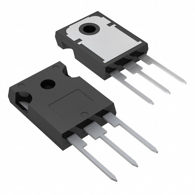
The IRGP4263PBF is an Infineon Technologies IGBT rated for 650V collector-emitter breakdown voltage with 90A maximum collector current and 300W power dissipation in a TO-247-3 through-hole package. This device is classified as obsolete product status. Due to obsolescence, equivalent substitute parts from active product lines are necessary to maintain design continuity and ensure long-term supply chain reliability for applications requiring 650V IGBT functionality in TO-247 packaging.
Substiute Parts
Key Parameters
| Parameter | Value | Unit |
|---|---|---|
| Voltage - Collector Emitter Breakdown (Max) | 650 | V |
| Current - Collector (Ic) (Max) | 90 | A |
| Current - Collector Pulsed (Icm) | 192 | A |
| Vce(on) (Max) @ Vge, Ic | 2.1V @ 15V, 48A | V |
| Power - Max | 300 | W |
| Gate Charge | 150 | nC |
| Switching Energy (on/off) | 1.7mJ / 1mJ | mJ |
| Td (on/off) @ 25°C | 70ns / 140ns | ns |
| Operating Temperature Range | -40 to 175 | °C (TJ) |
| Mounting Type | Through Hole | - |
| Package / Case | TO-247-3 | - |
Substitute Part Grouping Explanation
Substitution of the IRGP4263PBF is determined by the following critical parameters:
Voltage Rating: All substitute parts must maintain 650V collector-emitter breakdown voltage to ensure safe operation within the original design specifications.
Current Rating: The original part specifies 90A maximum collector current. Substitute parts with equal or higher current ratings (80A minimum to 120A maximum) are acceptable, as they provide equivalent or enhanced current handling capability without requiring circuit redesign.
Package Type: All substitutes must use TO-247-3 through-hole packaging to ensure mechanical and thermal compatibility with existing PCB layouts and heatsink mounting configurations.
Operating Temperature Range: All substitute parts must support the -40°C to 175°C junction temperature range to maintain thermal performance across the application's operating envelope.
Input Type: All parts maintain Standard input type configuration, ensuring gate drive circuit compatibility.
Mounting Configuration: Through-hole mounting is maintained across all substitutes for direct mechanical compatibility.
Substitute parts are grouped into two categories: (1) Infineon TrenchStop® technology parts offering improved switching characteristics, and (2) alternative manufacturer parts (STMicroelectronics, onsemi, IXYS) providing equivalent electrical performance with different process technologies.
Parameter Comparison
| Parameter | IRGP4263PBF | IGW60N60H3FKSA1 | IKW50N65F5FKSA1 | STGW60H65FB | FGH60T65SHD-F155 | IXYH40N65C3H1 | STGW40H65DFB | STGW60H65DFB | STGW80H65DFB |
|---|---|---|---|---|---|---|---|---|---|
| Voltage - Collector Emitter Breakdown (Max) | 650V | 600V | 650V | 650V | 650V | 650V | 650V | 650V | 650V |
| Current - Collector (Ic) (Max) | 90A | 80A | 80A | 80A | 120A | 80A | 80A | 80A | 120A |
| Current - Collector Pulsed (Icm) | 192A | 180A | 150A | 240A | 180A | 180A | 160A | 240A | 240A |
| Vce(on) (Max) @ Vge, Ic | 2.1V @ 15V, 48A | 2.3V @ 15V, 60A | 2.1V @ 15V, 50A | 2.3V @ 15V, 60A | 2.1V @ 15V, 60A | 2.2V @ 15V, 40A | 2.0V @ 15V, 40A | 2.0V @ 15V, 60A | 2.0V @ 15V, 80A |
| Power - Max | 300W | 416W | 305W | 375W | 349W | 300W | 283W | 375W | 469W |
| Gate Charge | 150nC | 375nC | 120nC | 306nC | 102nC | 70nC | 210nC | 306nC | 414nC |
| Switching Energy (on/off) | 1.7mJ / 1mJ | 2.1mJ / 1.13mJ | 490µJ / 160µJ | 1.09mJ / 626µJ | 1.69mJ / 630µJ | 860µJ / 400µJ | 498µJ / 363µJ | 1.09mJ / 626µJ | 2.1mJ / 1.5mJ |
| Td (on/off) @ 25°C | 70ns / 140ns | 27ns / 252ns | 21ns / 175ns | 51ns / 160ns | 26ns / 87ns | 26ns / 106ns | 40ns / 142ns | 51ns / 160ns | 84ns / 280ns |
| Operating Temperature Range | -40 to 175°C | -40 to 175°C | -40 to 175°C | -55 to 175°C | -55 to 175°C | - | -55 to 175°C | -55 to 175°C | -55 to 175°C |
| Package / Case | TO-247-3 | TO-247-3 | TO-247-3 | TO-247-3 | TO-247-3 | TO-247-3 | TO-247-3 | TO-247-3 | TO-247-3 |
| Product Status | Obsolete | Active | Active | Active | Active | Active | Active | Active | Active |
| RoHS Status | - | ROHS3 Compliant | ROHS3 Compliant | ROHS3 Compliant | ROHS3 Compliant | ROHS3 Compliant | ROHS3 Compliant | ROHS3 Compliant | ROHS3 Compliant |
Engineering Selection Recommendations
Primary Substitutes (Highest Compatibility):
IKW50N65F5FKSA1 and STGW60H65DFB are the preferred substitutes. Both maintain 650V voltage rating, 80A collector current (within acceptable range of original 90A specification), and TO-247-3 packaging. IKW50N65F5FKSA1 offers lower gate charge (120nC versus 150nC) and reduced switching energy, resulting in improved efficiency. STGW60H65DFB provides higher pulsed current capability (240A) and is available in high inventory (27,100 units). Both parts are ROHS3 compliant and carry Active product status.
Secondary Substitutes (Acceptable with Design Verification):
STGW40H65DFB and IXYH40N65C3H1 provide equivalent 650V/80A ratings with lower on-state voltage (2.0V and 2.2V respectively) compared to the original 2.1V specification. These parts reduce conduction losses in high-current applications. STGW40H65DFB offers the lowest on-state voltage (2.0V @ 15V, 40A) and is available in substantial inventory (6,560 units).
Higher Current Alternative:
FGH60T65SHD-F155 and STGW80H65DFB support 120A collector current, exceeding the original 90A rating. These parts are suitable for applications requiring enhanced current margin or future design scaling. FGH60T65SHD-F155 offers superior switching speed (26ns turn-on, 87ns turn-off) and is available in the highest inventory (23,300 units).
Voltage Derating Consideration:
IGW60N60H3FKSA1 operates at 600V maximum breakdown voltage, representing a 50V reduction from the original 650V specification. This part is acceptable only for applications with confirmed 600V maximum operating voltage and appropriate design margin verification.
All substitute parts maintain Standard input type, through-hole mounting, and operating temperature range compatibility with the original IRGP4263PBF specification.
Frequently Asked Questions (FAQ)
Q: Can I use a substitute part with lower collector current rating than the original 90A specification?
A: Yes. Substitute parts rated at 80A collector current are acceptable if the application's actual operating current does not exceed 80A. The original 90A rating provides design margin; substitutes with 80A ratings maintain this margin for most applications. Verify actual circuit current requirements before selection.
Q: What is the significance of the 600V rating on IGW60N60H3FKSA1 compared to the original 650V?
A: The 50V difference represents a voltage derating. IGW60N60H3FKSA1 is suitable only for applications with confirmed maximum operating voltage of 600V or lower. For applications requiring full 650V capability, select substitutes with 650V ratings: IKW50N65F5FKSA1, STGW60H65FB, STGW60H65DFB, STGW40H65DFB, FGH60T65SHD-F155, or IXYH40N65C3H1.
Q: Are all substitute parts mechanically compatible with the original TO-247-3 footprint?
A: Yes. All listed substitute parts use TO-247-3 or equivalent TO-247 packaging, ensuring direct mechanical compatibility with existing PCB layouts and heatsink mounting configurations. Verify supplier device package designation matches your PCB design requirements.
Q: Which substitute offers the best switching performance?
A: FGH60T65SHD-F155 provides the fastest switching characteristics with 26ns turn-on delay and 87ns turn-off delay. IXYH40N65C3H1 also offers rapid switching (26ns turn-on, 106ns turn-off) with the lowest gate charge (70nC), reducing gate drive circuit power requirements.
Q: What is the difference between Trench, Trench Field Stop, and PT IGBT types among the substitutes?
A: IGBT type designates the internal semiconductor structure and manufacturing process. Trench (IGW60N60H3FKSA1), Trench Field Stop (STGW60H65FB, STGW60H65DFB, STGW40H65DFB, STGW80H65DFB, FGH60T65SHD-F155), and PT (IXYH40N65C3H1) represent different technology generations. All types are electrically compatible with the original IRGP4263PBF for the specified voltage and current parameters. Selection depends on switching speed requirements and gate charge tolerance in your application.
Q: Why do some substitutes have higher power ratings than the original 300W specification?
A: Power rating reflects maximum dissipation capability under specified test conditions. Higher power ratings indicate improved thermal performance or larger die size. Substitutes with 375W, 416W, 469W ratings provide enhanced thermal margin and are suitable for applications with higher continuous current or ambient temperature requirements.
Q: Are all substitute parts RoHS3 compliant?
A: Yes. All active substitute parts listed carry ROHS3 Compliant status. The original IRGP4263PBF does not specify RoHS status due to obsolete product classification. All substitutes meet current environmental compliance requirements.
Q: Which substitute has the lowest on-state voltage loss?
A: STGW40H65DFB and STGW80H65DFB both specify 2.0V on-state voltage at 15V gate drive, representing a 0.1V reduction compared to the original 2.1V specification. This reduction decreases conduction losses in high-current applications. IXYH40N65C3H1 specifies 2.2V, and IKW50N65F5FKSA1 matches the original 2.1V specification.
Q: Can I use STGW80H65DFB as a direct replacement for IRGP4263PBF?
A: STGW80H65DFB is electrically compatible but operates at 120A collector current versus the original 90A. This higher current rating provides design margin and is suitable for applications requiring enhanced current capacity. Verify gate drive circuit can supply the higher gate charge (414nC versus 150nC) before implementation.
Alternative Parts

SJ6012L2TP
Littelfuse Inc.
6 Alternative Parts

JMK107BBJ476MA-RE
Taiyo Yuden
10 Alternative Parts

GMK107BBJ475MA-T
Taiyo Yuden
5 Alternative Parts
SJ6020N2ARP
Littelfuse Inc.
3 Alternative Parts
SJ6025R2ATP
Littelfuse Inc.
4 Alternative Parts

2474-05L
API Delevan Inc.
1 Alternative Parts

4590R-684K
API Delevan Inc.
1 Alternative Parts

CM6560R-334
API Delevan Inc.
1 Alternative Parts

CM6460-104
API Delevan Inc.
1 Alternative Parts

5526-12
API Delevan Inc.
1 Alternative Parts