


Request Quote
(Ships tomorrow)
IRGP4263DPBF IGBT Equivalent & Substitute Parts
Part Overview
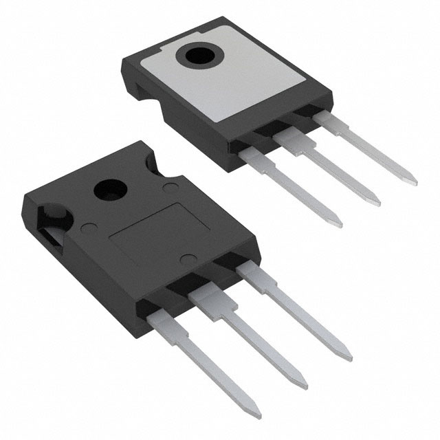
The IRGP4263DPBF is a 650V, 90A IGBT manufactured by Infineon Technologies in TO-247-3 package configuration. This device is classified as obsolete, indicating it is no longer in active production. The part delivers 325W maximum power dissipation and is designed for through-hole mounting applications requiring high-voltage switching capability.
Due to its obsolete status, identifying functionally equivalent substitute components is necessary for design continuity, system maintenance, and procurement of replacement inventory. Substitute parts must maintain compatibility across voltage rating, current capacity, thermal characteristics, and package form factor to ensure direct replacement capability.
Substiute Parts
Key Parameters
| Parameter | Value | Unit |
|---|---|---|
| Voltage - Collector Emitter Breakdown (Max) | 650 | V |
| Current - Collector (Ic) (Max) | 90 | A |
| Current - Collector Pulsed (Icm) | 192 | A |
| Power - Max | 325 | W |
| Vce(on) (Max) @ Vge, Ic | 2.1V @ 15V, 48A | V |
| Gate Charge | 145 | nC |
| Switching Energy (on/off) | 2.9mJ / 1.4mJ | mJ |
| Td (on/off) @ 25°C | 70ns / 140ns | ns |
| Reverse Recovery Time (trr) | 170 | ns |
| Operating Temperature Range | -40 to 175 | °C |
| Package / Case | TO-247-3 | - |
| Mounting Type | Through Hole | - |
Substitute Part Grouping Explanation
Substitution of the IRGP4263DPBF is determined by the following critical parameters:
Voltage Rating: The collector-emitter breakdown voltage must equal or exceed 650V. Parts rated at 600V do not meet this requirement and are not suitable direct substitutes.
Current Capacity: The maximum collector current (Ic) must support the 90A requirement. Parts with lower current ratings (80A) represent reduced capability and are not direct equivalents.
Package Configuration: All substitute parts must use TO-247-3 package with through-hole mounting to ensure mechanical and thermal compatibility.
Power Dissipation: Maximum power rating should be comparable to 325W to maintain thermal design margins.
Operating Temperature: The -40°C to 175°C junction temperature range must be maintained or exceeded.
Input Type: Standard gate input configuration is required for gate drive compatibility.
Based on these criteria, the following substitute parts meet the electrical and mechanical requirements:
- IXXH60N65C4: 650V, 118A, 455W, TO-247-3, Active status
- IXXH40N65B4: 650V, 120A, 455W, TO-247-3, Active status
- IKW50N65F5FKSA1: 650V, 80A, 305W, TO-247-3, Active status
- IXYH40N65C3H1: 650V, 80A, 300W, TO-247-3, Active status
Parts with 600V rating (IKW50N60DTPXKSA1) and those with lower current capacity do not qualify as direct substitutes due to voltage or current specification mismatches.
Parameter Comparison
| Parameter | IRGP4263DPBF | IXXH60N65C4 | IXXH40N65B4 | IKW50N65F5FKSA1 | IXYH40N65C3H1 |
|---|---|---|---|---|---|
| Manufacturer | Infineon | IXYS | IXYS | Infineon | IXYS |
| Voltage - Collector Emitter Breakdown (Max) | 650V | 650V | 650V | 650V | 650V |
| Current - Collector (Ic) (Max) | 90A | 118A | 120A | 80A | 80A |
| Current - Collector Pulsed (Icm) | 192A | 240A | 240A | 150A | 180A |
| Power - Max | 325W | 455W | 455W | 305W | 300W |
| Vce(on) (Max) @ Vge, Ic | 2.1V @ 15V, 48A | 2.2V @ 15V, 60A | 1.8V @ 15V, 40A | 2.1V @ 15V, 50A | 2.2V @ 15V, 40A |
| Gate Charge | 145nC | 94nC | 77nC | 120nC | 70nC |
| Switching Energy (on/off) | 2.9mJ / 1.4mJ | 3.2mJ / 830µJ | 1.4mJ / 560µJ | 490µJ / 160µJ | 860µJ / 400µJ |
| Td (on/off) @ 25°C | 70ns / 140ns | 37ns / 133ns | 28ns / 144ns | 21ns / 175ns | 26ns / 106ns |
| Operating Temperature Range | -40 to 175°C | -55 to 175°C | -55 to 175°C | -40 to 175°C | - |
| Package / Case | TO-247-3 | TO-247-3 | TO-247-3 | TO-247-3 | TO-247-3 |
| Product Status | Obsolete | Active | Active | Active | Active |
| RoHS Status | - | ROHS3 Compliant | ROHS3 Compliant | ROHS3 Compliant | ROHS3 Compliant |
Engineering Selection Recommendations
IXXH60N65C4 (IXYS, Active): This part exceeds the original specification with 118A continuous current and 455W power rating. The device maintains 650V voltage rating and TO-247-3 package compatibility. ROHS3 compliance and active product status ensure long-term availability. Gate charge of 94nC is lower than the original, reducing gate drive power requirements. This part is suitable for applications where higher current capacity provides design margin.
IXXH40N65B4 (IXYS, Active): Rated at 120A continuous current with 455W power dissipation, this part provides the highest current capacity among available substitutes. The 1.8V Vce(on) specification is lower than the original, resulting in reduced conduction losses. ROHS3 compliance and active status support procurement continuity. Switching energy characteristics are favorable for high-frequency applications.
IKW50N65F5FKSA1 (Infineon, Active): This Infineon TrenchStop® device maintains manufacturer continuity with the original part. The 80A current rating is below the original 90A specification but remains within acceptable range for many applications. The 305W power rating and significantly reduced switching energy (490µJ on, 160µJ off) indicate improved efficiency characteristics. ROHS3 compliance and active product status ensure availability. This part is recommended for applications prioritizing switching performance and thermal efficiency.
IXYH40N65C3H1 (IXYS, Active): Rated at 80A with 300W power dissipation, this part represents a lower-current alternative. The 70nC gate charge is the lowest among substitutes, minimizing gate drive requirements. ROHS3 compliance and active status support long-term procurement. This part is suitable for applications with reduced current demands or where gate drive power is a design constraint.
Product Status Consideration: All recommended substitutes carry Active product status, ensuring availability and long-term support compared to the obsolete IRGP4263DPBF. All parts maintain ROHS3 compliance and REACH unaffected status, meeting environmental and regulatory requirements.
Frequently Asked Questions (FAQ)
Q: Can the IRGP4263DPBF be directly replaced with a 600V-rated IGBT?
A: No. The original part is rated for 650V collector-emitter breakdown voltage. Substitutes must maintain this voltage rating or higher to ensure safe operation under maximum voltage stress conditions. 600V-rated devices do not meet this requirement.
Q: What is the significance of the 90A current rating in selecting substitutes?
A: The 90A continuous collector current is a critical design parameter. Substitute parts must support this current level or higher to maintain equivalent thermal and electrical performance. Parts rated below 90A (such as 80A devices) represent reduced current capacity and may not be suitable for all applications, though they can function in circuits with lower current demands.
Q: Are TO-247-3 and TO-247-AD packages interchangeable?
A: Both TO-247-3 and TO-247-AD are through-hole TO-247 variants with identical pin configurations and mechanical compatibility. The designations reflect different supplier packaging specifications but are mechanically and electrically compatible for PCB mounting and thermal management purposes.
Q: How do switching energy differences affect circuit performance?
A: Switching energy (on and off) directly impacts gate drive power requirements and switching losses. Lower switching energy values reduce thermal dissipation and improve efficiency at high switching frequencies. The IKW50N65F5FKSA1 exhibits significantly lower switching energy compared to the original part, making it advantageous for high-frequency applications.
Q: What does ROHS3 compliance indicate?
A: ROHS3 compliance certifies that the device meets Restriction of Hazardous Substances Directive requirements, restricting lead, cadmium, mercury, and other hazardous materials. All recommended substitutes carry ROHS3 certification, ensuring compliance with environmental regulations and supporting procurement for regulated applications.
Q: Can a higher-rated substitute part cause circuit malfunction?
A: No. Substitute parts with higher current ratings (120A vs. 90A) or higher power dissipation (455W vs. 325W) do not cause malfunction. These higher ratings provide design margin and improved thermal performance. The critical requirement is that voltage rating and package configuration remain compatible with the original circuit design.
Q: Why is product status important when selecting substitutes?
A: Active product status indicates ongoing manufacturing, quality assurance, and long-term availability. The original IRGP4263DPBF is obsolete, meaning production has ceased and inventory is limited. All recommended substitutes carry Active status, ensuring reliable procurement for current and future production needs.
Q: How does gate charge affect gate driver selection?
A: Gate charge (measured in nanocoulombs) determines the total charge required to switch the IGBT on and off. Lower gate charge reduces gate drive power and allows faster switching with lower-power gate drivers. Substitute parts range from 70nC to 120nC, all compatible with standard 15V gate drive circuits used in the original design.
Alternative Parts

SJ6012L2TP
Littelfuse Inc.
6 Alternative Parts

JMK107BBJ476MA-RE
Taiyo Yuden
10 Alternative Parts

GMK107BBJ475MA-T
Taiyo Yuden
5 Alternative Parts
SJ6020N2ARP
Littelfuse Inc.
3 Alternative Parts
SJ6025R2ATP
Littelfuse Inc.
4 Alternative Parts

2474-05L
API Delevan Inc.
1 Alternative Parts

4590R-684K
API Delevan Inc.
1 Alternative Parts

CM6560R-334
API Delevan Inc.
1 Alternative Parts

CM6460-104
API Delevan Inc.
1 Alternative Parts

5526-12
API Delevan Inc.
1 Alternative Parts