


Request Quote
(Ships tomorrow)
IRGP4069PBF IGBT Equivalent & Substitute Parts
Part Overview
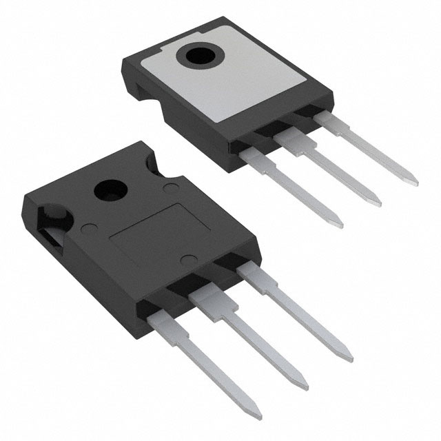
The IRGP4069PBF is a Trench IGBT manufactured by Infineon Technologies, rated for 600V collector-emitter breakdown voltage with 76A maximum collector current and 268W power dissipation in a TO-247AC through-hole package. This device is classified as Obsolete, necessitating identification of functionally equivalent alternatives for ongoing system support and new production requirements. Substitute parts must maintain electrical compatibility within the 600V voltage class while accommodating the thermal and switching characteristics of the original application circuit.
Substiute Parts
Key Parameters
| Parameter | Value | Unit |
|---|---|---|
| Voltage - Collector Emitter Breakdown (Max) | 600 | V |
| Current - Collector (Ic) (Max) | 76 | A |
| Current - Collector Pulsed (Icm) | 105 | A |
| Vce(on) (Max) @ Vge, Ic | 1.85V @ 15V, 35A | V |
| Power - Max | 268 | W |
| Switching Energy (on/off) | 390µJ / 632µJ | µJ |
| Gate Charge | 104 | nC |
| Td (on/off) @ 25°C | 46ns / 105ns | ns |
| Operating Temperature Range | -55 to 175 | °C |
| Package / Case | TO-247-3 | |
| Mounting Type | Through Hole |
Substitute Part Grouping Explanation
Substitution eligibility for the IRGP4069PBF is determined by the following critical parameters:
Voltage Class Compatibility: All substitute parts must maintain 600V or higher collector-emitter breakdown voltage rating to ensure safe operation within the original circuit voltage envelope.
Current Rating Compatibility: Substitute parts must provide collector current ratings of 76A or greater to accommodate the original design current requirements without derating.
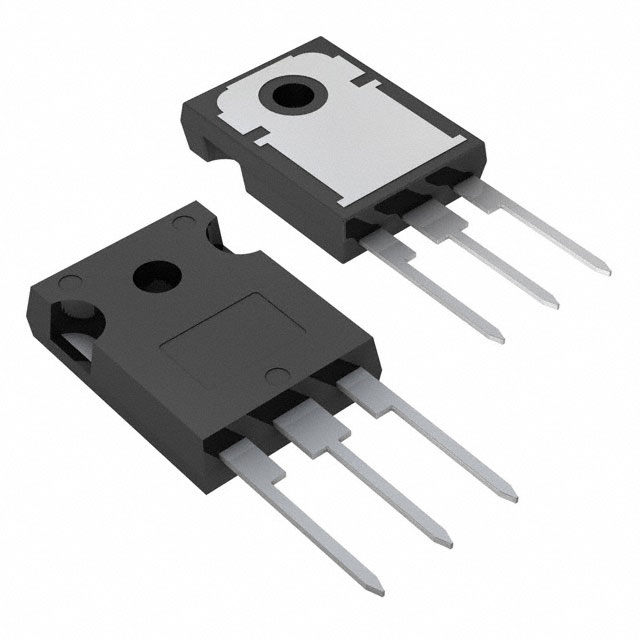
Package Compatibility: All substitutes must use TO-247-3 through-hole packaging to ensure mechanical and thermal interface compatibility with existing PCB layouts and heatsink assemblies.
Thermal Performance: Maximum power dissipation ratings must be evaluated against the original 268W specification to ensure adequate thermal management within the application's cooling infrastructure.
Switching Characteristics: Gate charge, switching delay times, and switching energy parameters influence gate driver circuit design and must be within acceptable ranges for the existing driver implementation.
The three identified substitute parts meet these core substitution criteria while offering varying levels of performance enhancement and product lifecycle status.
Parameter Comparison
| Parameter | IRGP4069PBF (Original) | IGW50N60TPXKSA1 | STGW60H65FB | IXGH72N60A3 |
|---|---|---|---|---|
| Manufacturer | Infineon Technologies | Infineon Technologies | STMicroelectronics | IXYS |
| IGBT Type | Trench | Trench Field Stop | Trench Field Stop | PT |
| Voltage - Collector Emitter Breakdown (Max) | 600 V | 600 V | 650 V | 600 V |
| Current - Collector (Ic) (Max) | 76 A | 80 A | 80 A | 75 A |
| Current - Collector Pulsed (Icm) | 105 A | 150 A | 240 A | 400 A |
| Vce(on) (Max) @ Vge, Ic | 1.85V @ 15V, 35A | 1.8V @ 15V, 50A | 2.3V @ 15V, 60A | 1.35V @ 15V, 60A |
| Power - Max | 268 W | 319.2 W | 375 W | 540 W |
| Switching Energy (on) | 390 µJ | 1.53 mJ | 1.09 mJ | 1.38 mJ |
| Switching Energy (off) | 632 µJ | 850 µJ | 626 µJ | 3.5 mJ |
| Gate Charge | 104 nC | 249 nC | 306 nC | 230 nC |
| Td (on/off) @ 25°C | 46ns / 105ns | 20ns / 215ns | 51ns / 160ns | 31ns / 320ns |
| Operating Temperature Range | -55 to 175°C | -40 to 175°C | -55 to 175°C | -55 to 150°C |
| Package / Case | TO-247-3 | TO-247-3 | TO-247-3 | TO-247-3 |
| Product Status | Obsolete | Not For New Designs | Active | Active |
| RoHS Status | Not Specified | ROHS3 Compliant | ROHS3 Compliant | ROHS3 Compliant |
Engineering Selection Recommendations
For Existing System Maintenance: The IGW50N60TPXKSA1 provides the closest electrical match to the IRGP4069PBF within the Infineon product family. However, this part carries "Not For New Designs" status, limiting its suitability for long-term production support. The higher gate charge (249 nC vs. 104 nC) and increased switching energy on-time (1.53 mJ vs. 390 µJ) require gate driver circuit evaluation to confirm compatibility with existing driver specifications.
For Active Production and New Designs: The STGW60H65FB from STMicroelectronics is the recommended primary substitute. This part maintains Active product status, ensuring long-term availability and supply chain stability. The 650V voltage rating provides additional design margin above the original 600V specification. RoHS3 compliance and REACH compliance align with current regulatory requirements. The switching energy profile (1.09 mJ on, 626 µJ off) closely matches the original device, minimizing gate driver circuit modifications. Operating temperature range (-55 to 175°C) matches the original specification.
For High-Performance Applications: The IXGH72N60A3 from IXYS offers superior thermal performance (540W maximum power dissipation) and lower on-state voltage (1.35V @ 15V, 60A), reducing conduction losses. Active product status and RoHS3 compliance support production continuity. The significantly higher off-time switching energy (3.5 mJ vs. 632 µJ) and extended turn-off delay (320ns vs. 105ns) require detailed gate driver circuit analysis. The maximum operating temperature of 150°C is 25°C lower than the original specification, which may impact thermal design margins in high-temperature applications.
All substitute parts are available in standard through-hole TO-247-3 packaging, ensuring mechanical compatibility with existing PCB layouts and heatsink assemblies.
Frequently Asked Questions (FAQ)
Q: Can the IGW50N60TPXKSA1 be used as a direct replacement for the IRGP4069PBF?
A: The IGW50N60TPXKSA1 meets the core electrical requirements: 600V voltage rating, 80A collector current (exceeding the 76A requirement), and TO-247-3 packaging. However, the "Not For New Designs" status indicates this part is in end-of-life phase. The higher gate charge (249 nC vs. 104 nC) and increased on-time switching energy (1.53 mJ vs. 390 µJ) require verification that the existing gate driver circuit can accommodate these parameters without performance degradation.
Q: Why does the STGW60H65FB have a higher voltage rating (650V) than the original IRGP4069PBF (600V)?
A: The 650V rating provides additional voltage margin for circuit protection and transient overvoltage conditions. This higher rating does not create incompatibility; the device operates safely at 600V and below. The higher voltage rating is a design advantage for system reliability.
Q: What is the impact of different gate charge values on circuit design?
A: Gate charge directly affects the energy required to switch the IGBT on and off. The IRGP4069PBF requires 104 nC, while substitutes range from 249 nC to 306 nC. Higher gate charge increases gate driver power dissipation and may require gate driver circuit modifications to maintain switching speed and efficiency. Gate driver current capability must be verified against the substitute part's gate charge specification.
Q: Are all substitute parts RoHS3 compliant?
A: Yes. The IGW50N60TPXKSA1, STGW60H65FB, and IXGH72N60A3 are all RoHS3 compliant. The original IRGP4069PBF RoHS status is not specified in the provided data.
Q: Which substitute part is recommended for new product designs?
A: The STGW60H65FB is recommended for new designs. It maintains Active product status, ensuring long-term availability and supply chain support. RoHS3 compliance and REACH compliance satisfy current regulatory requirements. The switching energy profile closely matches the original device, minimizing gate driver circuit redesign.
Q: Can the IXGH72N60A3 be used in applications requiring operation above 150°C?
A: No. The IXGH72N60A3 maximum operating temperature is 150°C, which is 25°C lower than the original IRGP4069PBF specification of 175°C. Applications requiring sustained operation above 150°C must use the STGW60H65FB or IGW50N60TPXKSA1, both rated to 175°C.
Q: Do all substitute parts use the same TO-247-3 package?
A: Yes. All substitute parts use TO-247-3 through-hole packaging, ensuring mechanical and thermal interface compatibility with existing PCB layouts and heatsink assemblies. No mechanical redesign is required for package substitution.
Q: What is the significance of the "PT" IGBT type designation for the IXGH72N60A3?
A: PT (Punch-Through) is a different IGBT technology compared to the Trench and Trench Field Stop types used in other substitutes. The PT technology in the IXGH72N60A3 delivers lower on-state voltage (1.35V) but exhibits higher off-time switching energy (3.5 mJ). This technology trade-off reduces conduction losses at the cost of increased switching losses, requiring application-specific evaluation.
Alternative Parts

SJ6012L2TP
Littelfuse Inc.
6 Alternative Parts

JMK107BBJ476MA-RE
Taiyo Yuden
10 Alternative Parts

GMK107BBJ475MA-T
Taiyo Yuden
5 Alternative Parts
SJ6020N2ARP
Littelfuse Inc.
3 Alternative Parts
SJ6025R2ATP
Littelfuse Inc.
4 Alternative Parts

2474-05L
API Delevan Inc.
1 Alternative Parts

4590R-684K
API Delevan Inc.
1 Alternative Parts

CM6560R-334
API Delevan Inc.
1 Alternative Parts

CM6460-104
API Delevan Inc.
1 Alternative Parts

5526-12
API Delevan Inc.
1 Alternative Parts