


Request Quote
(Ships tomorrow)
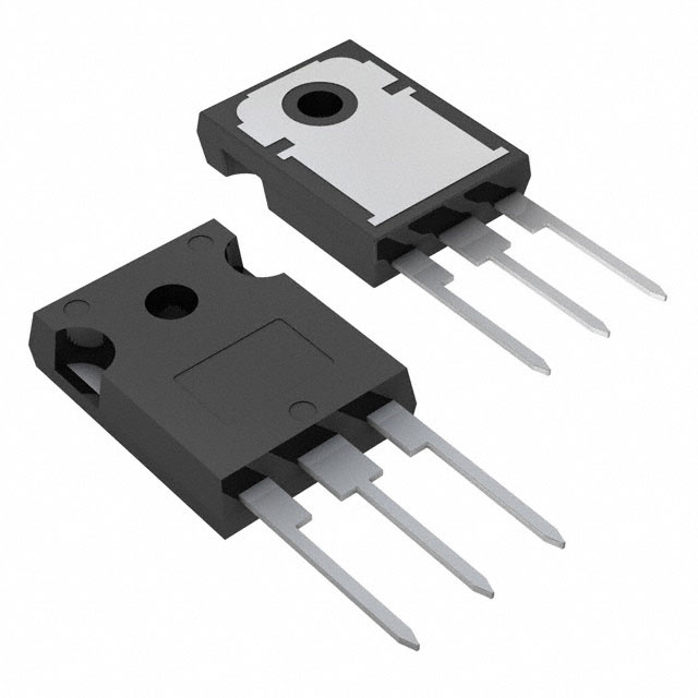
IRG4PC40KDPBF IGBT 600V 42A Equivalent & Substitute Parts
Part Overview
The IRG4PC40KDPBF is an Infineon Technologies IGBT transistor rated for 600V collector-emitter breakdown voltage with 42A maximum collector current and 160W power dissipation in a through-hole TO-247AC package. This device is classified as obsolete, necessitating identification of active equivalent and substitute components for new designs and production continuity. Substitute parts must maintain electrical compatibility within the 600V voltage class while accommodating the 42A current specification and TO-247 package family.
Substiute Parts
Key Parameters
| Parameter | Value | Unit |
|---|---|---|
| Voltage - Collector Emitter Breakdown (Max) | 600 | V |
| Current - Collector (Ic) (Max) | 42 | A |
| Current - Collector Pulsed (Icm) | 84 | A |
| Power - Max | 160 | W |
| Vce(on) (Max) @ Vge, Ic | 2.6V @ 15V, 25A | V |
| Gate Charge | 120 | nC |
| Switching Energy (on/off) | 950 / 760 | µJ |
| Td (on/off) @ 25°C | 53 / 110 | ns |
| Operating Temperature Range | -55 to 150 | °C (TJ) |
| Mounting Type | Through Hole | - |
| Package / Case | TO-247-3 | - |
| RoHS Status | ROHS3 Compliant | - |
Substitute Part Grouping Explanation
Substitution of the IRG4PC40KDPBF is determined by strict adherence to the following electrical and mechanical criteria:
Primary Substitution Criteria:
- Voltage rating: 600V collector-emitter breakdown voltage (mandatory)
- Current rating: Minimum 42A continuous collector current
- Package: TO-247 family (TO-247-3, TO-247AC, TO-247AD, TO-247 Long Leads)
- Mounting: Through-hole configuration
- Input type: Standard gate drive
- Compliance: ROHS3 compliant, REACH unaffected
Secondary Compatibility Factors:
- Operating temperature range: Minimum -55°C to 150°C junction temperature
- Vce(on) saturation voltage: Devices with Vce(on) ≤ 2.6V @ rated conditions
- Gate charge: Acceptable range for standard gate drive circuits
- Switching characteristics: Compatible with 10Ω gate resistance circuits
The substitute parts listed below meet all primary criteria and maintain electrical compatibility within the specified parameter ranges.
Parameter Comparison
| Parameter | IRG4PC40KDPBF (Main) | APT15GT60BRDQ1G | IXXH30N60B3D1 | IXXH30N60C3D1 | STGW19NC60HD | STGW20V60DF | STGW30H60DFB | STGW40H60DLFB |
|---|---|---|---|---|---|---|---|---|
| Manufacturer | Infineon | Microchip | IXYS | IXYS | STMicroelectronics | STMicroelectronics | STMicroelectronics | STMicroelectronics |
| Voltage (V) | 600 | 600 | 600 | 600 | 600 | 600 | 600 | 600 |
| Current - Ic (A) | 42 | 42 | 60 | 60 | 42 | 40 | 60 | 80 |
| Current - Icm (A) | 84 | 45 | 115 | 110 | 60 | 80 | 120 | 160 |
| Power - Max (W) | 160 | 184 | 270 | 270 | 140 | 167 | 260 | 283 |
| Vce(on) (V) | 2.6 @ 15V, 25A | 2.5 @ 15V, 15A | 1.85 @ 15V, 24A | 2.3 @ 15V, 24A | 2.5 @ 15V, 12A | 2.2 @ 15V, 20A | 2.0 @ 15V, 30A | 2.0 @ 15V, 40A |
| Gate Charge (nC) | 120 | 75 | 39 | 37 | 53 | 116 | 149 | 210 |
| Switching Energy On (µJ) | 950 | 150 | 550 | 500 | 85 | 200 | 383 | - |
| Switching Energy Off (µJ) | 760 | 215 | 500 | 270 | 189 | 130 | 293 | 363 |
| Td(on) (ns) | 53 | 6 | 23 | 23 | 25 | 38 | 37 | - |
| Td(off) (ns) | 110 | 105 | 97 | 77 | 97 | 149 | 146 | 142 |
| Operating Temperature (°C) | -55 to 150 | -55 to 150 | -55 to 175 | -55 to 175 | -55 to 150 | -55 to 175 | -55 to 175 | -55 to 175 |
| Package | TO-247AC | TO-247 [B] | TO-247AD (IXXH) | TO-247AD (IXXH) | TO-247 Long Leads | TO-247-3 | TO-247 | TO-247 |
| Product Status | Obsolete | Active | Active | Active | Active | Active | Active | Active |
| RoHS Status | ROHS3 Compliant | ROHS3 Compliant | ROHS3 Compliant | ROHS3 Compliant | ROHS3 Compliant | ROHS3 Compliant | ROHS3 Compliant | ROHS3 Compliant |
Engineering Selection Recommendations
Direct Equivalent (Closest Match):
APT15GT60BRDQ1G (Microchip Technology) provides the closest electrical equivalence to the IRG4PC40KDPBF. This device maintains identical 600V/42A ratings with superior switching performance (6ns turn-on delay versus 53ns) and lower gate charge (75nC versus 120nC). The Thunderbolt IGBT® series classification indicates active product status with full ROHS3 compliance and REACH unaffected designation. Operating temperature range matches the original specification (-55°C to 150°C). Power rating of 184W exceeds the 160W requirement, providing thermal margin.
Higher Current Capability Alternatives:
STGW30H60DFB and IXXH30N60B3D1 both provide 60A continuous current rating with 600V voltage class, suitable for applications requiring current margin above the 42A specification. Both devices feature active product status, ROHS3 compliance, and extended operating temperature to 175°C. STGW30H60DFB offers lower Vce(on) (2.0V) and IXXH30N60B3D1 provides lowest gate charge (39nC) among substitutes.
Matched Current Rating Alternatives:
STGW19NC60HD maintains the 42A current specification with 600V rating and active product status. This device features the lowest switching energy (85µJ on-state, 189µJ off-state) among 42A-rated substitutes, reducing switching losses in high-frequency applications.
All substitute parts listed satisfy the following mandatory criteria:
- 600V collector-emitter breakdown voltage
- Minimum 42A continuous collector current
- TO-247 package family compatibility
- Through-hole mounting configuration
- ROHS3 compliance
- REACH unaffected status
- Standard gate drive input type
Frequently Asked Questions (FAQ)
Q: Can STGW40H60DLFB (80A) be used as a direct replacement for IRG4PC40KDPBF (42A)?
A: Yes, within electrical and thermal constraints. The 80A current rating provides substantial design margin. However, the higher gate charge (210nC versus 120nC) requires gate drive circuit verification to ensure adequate switching speed. The 283W power rating accommodates higher current operation. Mechanical fit in TO-247 package is compatible.
Q: What is the primary difference between IXXH30N60B3D1 and IXXH30N60C3D1?
A: Both devices share identical 600V/60A electrical ratings and TO-247AD package. The C3D1 variant exhibits lower switching energy off-state (270µJ versus 500µJ) and faster turn-off delay (77ns versus 97ns), resulting in reduced switching losses. Vce(on) is higher in C3D1 (2.3V versus 1.85V), increasing conduction losses. Selection depends on application priority: switching loss minimization (B3D1) or conduction loss minimization (C3D1).
Q: Are TO-247AC, TO-247 [B], and TO-247AD packages mechanically interchangeable?
A: All variants are mechanically compatible within the TO-247-3 family. Lead spacing and mounting hole patterns are standardized. Supplier device package designations (AC, [B], AD, Long Leads) indicate minor lead geometry variations that do not affect PCB mounting compatibility. Verify specific lead length requirements for your application.
Q: Why does APT15GT60BRDQ1G have significantly lower switching energy than IRG4PC40KDPBF?
A: The APT15GT60BRDQ1G represents a newer generation IGBT technology (Thunderbolt IGBT® series) with improved switching characteristics. Lower switching energy (150µJ on, 215µJ off versus 950µJ on, 760µJ off) reflects advances in semiconductor process technology and gate structure optimization. This results in reduced switching losses and improved efficiency in power conversion applications.
Q: What is the impact of gate charge differences on circuit design?
A: Gate charge (Qg) determines the charge quantity required to switch the IGBT fully on or off. Lower gate charge (APT15GT60BRDQ1G at 75nC, IXXH30N60B3D1 at 39nC) enables faster switching with lower gate drive current requirements. Higher gate charge (STGW40H60DLFB at 210nC) requires proportionally higher gate drive current or longer switching times. Gate drive circuit must supply sufficient current to achieve desired switching speed. Verify gate drive capability before substitution.
Q: Can devices with extended temperature range (-55°C to 175°C) replace those rated to 150°C?
A: Yes. Extended temperature range provides additional design margin and operational flexibility. Devices rated to 175°C (IXXH30N60B3D1, IXXH30N60C3D1, STGW20V60DF, STGW30H60DFB, STGW40H60DLFB) are fully compatible with applications limited to 150°C operation. No circuit modifications are required. Extended range may provide cost or availability advantages in long-term production.
Q: What does "Trench Field Stop" IGBT type indicate?
A: Trench Field Stop (TFS) is a semiconductor architecture used in STGW series devices (STGW20V60DF, STGW30H60DFB, STGW40H60DLFB). This design reduces reverse recovery current and improves switching performance compared to standard planar structures. TFS devices exhibit lower switching losses and improved thermal stability, making them suitable for high-frequency switching applications.
Q: Is inventory availability a factor in substitute selection?
A: Inventory levels provided (873 to 1873 pieces in stock across substitute parts) indicate current availability. However, engineering selection must prioritize electrical compatibility and product status (active versus obsolete) over inventory quantity. Consult with component suppliers for long-term availability and lead time commitments for production quantities.
Alternative Parts

SJ6012L2TP
Littelfuse Inc.
6 Alternative Parts

JMK107BBJ476MA-RE
Taiyo Yuden
10 Alternative Parts

GMK107BBJ475MA-T
Taiyo Yuden
5 Alternative Parts
SJ6020N2ARP
Littelfuse Inc.
3 Alternative Parts
SJ6025R2ATP
Littelfuse Inc.
4 Alternative Parts

2474-05L
API Delevan Inc.
1 Alternative Parts

4590R-684K
API Delevan Inc.
1 Alternative Parts

CM6560R-334
API Delevan Inc.
1 Alternative Parts

CM6460-104
API Delevan Inc.
1 Alternative Parts

5526-12
API Delevan Inc.
1 Alternative Parts