


Request Quote
(Ships tomorrow)
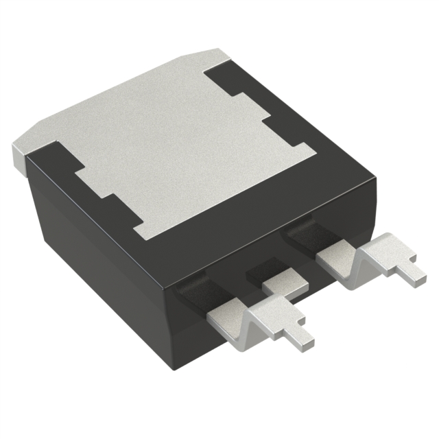
IRFS7540TRLPBF N-Channel 60V 110A MOSFET Equivalent & Substitute Parts
Part Overview
The IRFS7540TRLPBF is an N-Channel MOSFET manufactured by Infineon Technologies, rated for 60V drain-to-source voltage with 110A continuous drain current at 25°C. This device is packaged in D2PAK (TO-263-3) surface mount configuration and is part of the HEXFET® and StrongIRFET™ series. The part maintains Active product status with full RoHS3 compliance and unlimited moisture sensitivity level (MSL 1).
Substitute parts are necessary when the original IRFS7540TRLPBF becomes unavailable due to supply constraints, end-of-life transitions, or when design requirements permit operation within alternative electrical and mechanical specifications. Equivalent devices must maintain compatibility with the D2PAK package footprint and operate within the established voltage and current parameters of the application circuit.
Substiute Parts
Key Parameters
| Parameter | Value | Unit | Condition |
|---|---|---|---|
| Drain-to-Source Voltage (Vdss) | 60 | V | Maximum rating |
| Continuous Drain Current (Id) | 110 | A | @ 25°C (Tc) |
| On-State Resistance (Rds On) | 5.1 | mOhm | @ 65A, 10V Vgs |
| Gate Threshold Voltage (Vgs(th)) | 3.7 | V | @ 100µA Id |
| Gate Charge (Qg) | 130 | nC | @ 10V Vgs |
| Power Dissipation | 160 | W | @ Tc |
| Operating Temperature Range | -55 to 175 | °C | Junction temperature (TJ) |
| Package Type | D2PAK (TO-263-3) | — | Surface mount, 2 leads + tab |
| RoHS Status | ROHS3 Compliant | — | — |
Substitute Part Grouping Explanation
Substitution eligibility for the IRFS7540TRLPBF is determined by the following critical parameters:
Voltage Rating Compatibility: Substitute parts must have a Vdss rating equal to or greater than 60V. Parts rated at 55V operate below the original specification and are acceptable only when circuit design margins permit reduced voltage headroom.
Current Rating Compatibility: Substitute parts must support continuous drain current (Id) at or above 110A at 25°C. Parts with lower current ratings (75A, 80A, 100A) represent reduced current capacity and are suitable only for applications with lower current demands.
Package Compatibility: All substitute parts must use D2PAK (TO-263-3) or compatible D2PAK variants (TO-263AB, TO-263AA) to ensure PCB footprint compatibility. Package variants with different lead counts (TO-263-7, TO-263-8) are mechanically incompatible with standard D2PAK layouts.
On-State Resistance (Rds On): Substitute parts with Rds On values at or below 5.1mOhm at comparable test conditions (10V Vgs) maintain thermal performance equivalence. Higher Rds On values increase power dissipation and may require thermal design review.
Gate Charge (Qg): Substitute parts with gate charge at or below 130nC at 10V Vgs ensure compatible gate drive requirements and switching speed characteristics.
Compliance & Status: All substitute parts must maintain RoHS3 compliance, MSL 1 rating, and Active or equivalent product status to ensure long-term availability and regulatory alignment.
Parameter Comparison
| Part Number | Manufacturer | Vdss (V) | Id @ 25°C (A) | Rds On (mOhm) | Qg (nC) | Power Dissipation (W) | Package | Product Status |
|---|---|---|---|---|---|---|---|---|
| IRFS7540TRLPBF | Infineon | 60 | 110 | 5.1 | 130 | 160 | D2PAK (TO-263-3) | Active |
| BUK764R0-55B,118 | Nexperia USA Inc. | 55 | 75 | 4.0 | 86 | 300 | D2PAK | Active |
| IXFA220N06T3 | IXYS | 60 | 220 | 4.0 | 136 | 440 | TO-263 | Last Time Buy |
| IXFA230N075T2-7 | IXYS | 75 | 230 | 4.2 | 178 | 480 | TO-263-7 | Active |
| IXTA140N055T2 | IXYS | 55 | 140 | 5.4 | 82 | 250 | TO-263 (D2PAK) | Active |
| IXTA200N055T2 | IXYS | 55 | 200 | 4.2 | 109 | 360 | TO-263AA | Active |
| IXTA230N075T2-7 | IXYS | 75 | 230 | 4.2 | 178 | 480 | TO-263-7 | Active |
| STB100N6F7 | STMicroelectronics | 60 | 100 | 5.6 | 30 | 125 | TO-263 (D2PAK) | Active |
| STB130N6F7 | STMicroelectronics | 60 | 80 | 5.0 | 42 | 160 | TO-263 (D2PAK) | Active |
Engineering Selection Recommendations
Direct Voltage & Current Equivalents (Preferred Category):
IXFA220N06T3 (IXYS) matches the 60V voltage rating and exceeds the 110A current requirement at 220A continuous drain current. This part provides superior current capacity margin and identical voltage specification. However, the part carries Last Time Buy status, indicating limited future availability. Gate charge of 136nC is marginally higher than the original 130nC specification.
STB100N6F7 (STMicroelectronics) maintains 60V voltage rating with 100A continuous drain current, representing a 10A reduction from the original specification. This part is suitable for applications with confirmed current margins below 110A. Power dissipation is reduced to 125W, and gate charge is significantly lower at 30nC, enabling faster switching characteristics. Active product status ensures long-term supply continuity.
STB130N6F7 (STMicroelectronics) provides 60V voltage rating with 80A continuous drain current. This part is appropriate only for applications with confirmed current requirements below 80A. Gate charge of 42nC provides improved switching performance compared to the original device.
Reduced Voltage Alternatives (55V Rating):
BUK764R0-55B,118 (Nexperia USA Inc.) operates at 55V maximum Vdss with 75A continuous drain current. This part is suitable only when circuit design permits 5V reduction in voltage headroom. The device features lower Rds On (4.0mOhm) and reduced gate charge (86nC), with significantly higher power dissipation capability (300W). Automotive qualification (AEC-Q101) provides additional reliability assurance. Active product status confirms availability.
IXTA140N055T2 (IXYS) provides 55V rating with 140A continuous drain current, exceeding the original current specification. This part is compatible with applications accepting reduced voltage margin. Rds On of 5.4mOhm is slightly higher than the original specification, and gate charge of 82nC is lower. Active product status is maintained.
IXTA200N055T2 (IXYS) operates at 55V with 200A continuous drain current. This part offers substantial current margin for applications with reduced voltage tolerance. Rds On of 4.2mOhm and gate charge of 109nC provide favorable switching characteristics. Active product status ensures supply availability.
Higher Voltage Alternatives (75V Rating):
IXFA230N075T2-7 (IXYS) and IXTA230N075T2-7 (IXYS) both provide 75V voltage rating with 230A continuous drain current. These parts are suitable for applications requiring enhanced voltage margin. However, both parts use TO-263-7 package configuration with 7 leads, which is mechanically incompatible with standard D2PAK footprints designed for 3-lead packages. These parts are not recommended for direct PCB substitution without layout redesign.
Compliance & Availability Assessment:
All recommended substitute parts maintain RoHS3 compliance and MSL 1 rating, ensuring regulatory alignment and moisture handling compatibility with the original device. Parts with Active product status (BUK764R0-55B,118; IXTA140N055T2; IXTA200N055T2; STB100N6F7; STB130N6F7) provide superior long-term supply assurance compared to IXFA220N06T3, which carries Last Time Buy designation.
Frequently Asked Questions (FAQ)
Q: Can STB100N6F7 directly replace IRFS7540TRLPBF in my application?
A: STB100N6F7 is a direct package and voltage equivalent (both 60V, D2PAK) but provides 100A continuous drain current versus the original 110A specification. Direct substitution is possible only if your application circuit operates at or below 100A continuous current. Verify actual circuit current requirements before implementation. The lower gate charge (30nC vs. 130nC) may improve switching speed but requires gate drive circuit compatibility confirmation.
Q: Why are IXFA230N075T2-7 and IXTA230N075T2-7 listed if they use different packages?
A: These parts are listed because they appear in the manufacturer-provided substitute list for the IRFS7540TRLPBF. However, their TO-263-7 package configuration (7 leads) is mechanically incompatible with standard D2PAK PCB layouts designed for 3-lead TO-263-3 packages. These parts require complete PCB redesign and are not recommended for direct drop-in substitution. They are included for reference only in applications undergoing full redesign.
Q: Is BUK764R0-55B,118 acceptable as a substitute despite the 55V rating?
A: BUK764R0-55B,118 operates at 55V maximum Vdss, which is 5V below the original 60V specification. This part is acceptable only when circuit design analysis confirms that the application voltage never exceeds 55V under normal or fault conditions. If your circuit is designed for 60V operation with margin, this part introduces voltage headroom risk. Automotive qualification (AEC-Q101) provides additional reliability assurance for qualified applications.
Q: What is the significance of gate charge differences between substitute parts?
A: Gate charge (Qg) determines the amount of charge required to switch the MOSFET on and off. The original IRFS7540TRLPBF requires 130nC at 10V Vgs. Substitute parts with lower gate charge (STB100N6F7 at 30nC, STB130N6F7 at 42nC) switch faster and require less gate drive current, potentially improving efficiency. Parts with higher gate charge (IXFA220N06T3 at 136nC) require slightly more gate drive capability. Verify gate drive circuit compatibility with the selected substitute part's gate charge specification.
Q: Can I use IXTA200N055T2 if my application requires 110A at 60V?
A: IXTA200N055T2 provides 200A continuous drain current, exceeding the 110A requirement. However, it operates at 55V maximum Vdss, not 60V. This part is suitable only if your application circuit design permits 55V operation. If your circuit requires both 110A current and 60V voltage rating, IXFA220N06T3 (60V, 220A) is the appropriate choice, though it carries Last Time Buy status. For long-term supply assurance at 60V and 110A+ current, STB100N6F7 (100A) or IXFA220N06T3 are the only options; neither provides perfect equivalence.
Q: What does "Last Time Buy" status mean for IXFA220N06T3?
A: Last Time Buy status indicates that IXYS has announced end-of-life for this part. The manufacturer will accept orders for a limited time period before discontinuing production. Existing inventory may still be available, but future procurement will become impossible. For new designs or long-term applications, parts with Active status (STB100N6F7, STB130N6F7, BUK764R0-55B,118, IXTA series) are preferred to ensure supply continuity beyond the Last Time Buy window.
Q: Are all substitute parts RoHS3 compliant?
A: Yes. All substitute parts listed in this reference maintain RoHS3 compliance and MSL 1 (unlimited moisture sensitivity level) rating, matching the original IRFS7540TRLPBF specifications. This ensures regulatory alignment for applications subject to RoHS requirements and identical moisture handling procedures during assembly and storage.
Q: What is the practical difference between Rds On values of 4.0mOhm and 5.1mOhm?
A: On-state resistance (Rds On) directly affects power dissipation during conduction. At 100A continuous current, a 5.1mOhm device dissipates 51W (I²R = 100² × 0.0051), while a 4.0mOhm device dissipates 40W. The 11W difference may require thermal design adjustment. Lower Rds On values (BUK764R0-55B,118 at 4.0mOhm, IXTA200N055T2 at 4.2mOhm) reduce thermal load and may eliminate heatsink requirements in marginal designs. Higher Rds On values (STB100N6F7 at 5.6mOhm) increase thermal dissipation and may require enhanced cooling.
Alternative Parts

SJ6012L2TP
Littelfuse Inc.
6 Alternative Parts

JMK107BBJ476MA-RE
Taiyo Yuden
10 Alternative Parts

GMK107BBJ475MA-T
Taiyo Yuden
5 Alternative Parts
SJ6020N2ARP
Littelfuse Inc.
3 Alternative Parts
SJ6025R2ATP
Littelfuse Inc.
4 Alternative Parts

2474-05L
API Delevan Inc.
1 Alternative Parts

4590R-684K
API Delevan Inc.
1 Alternative Parts

CM6560R-334
API Delevan Inc.
1 Alternative Parts

CM6460-104
API Delevan Inc.
1 Alternative Parts

5526-12
API Delevan Inc.
1 Alternative Parts