


Request Quote
(Ships tomorrow)
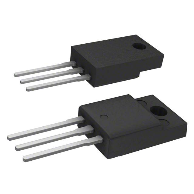
IRFS750A N-Channel 400V 8.4A MOSFET Equivalent & Substitute Parts
Part Overview
The IRFS750A is an N-Channel metal oxide semiconductor field-effect transistor (MOSFET) manufactured by onsemi, rated for 400V drain-to-source voltage and 8.4A continuous drain current at 25°C. The device is packaged in a TO-220F-3 through-hole configuration with a maximum power dissipation of 49W. The IRFS750A is classified as obsolete, necessitating identification of active equivalent and substitute components for new designs and ongoing production requirements. Substitute parts must maintain compatibility across critical electrical parameters including voltage rating, current capacity, gate charge characteristics, and thermal performance while accommodating through-hole mounting requirements.
Substiute Parts
Key Parameters
| Parameter | Value | Unit |
|---|---|---|
| Drain-to-Source Voltage (Vdss) | 400 | V |
| Continuous Drain Current (Id) @ 25°C | 8.4 | A |
| On-State Resistance (Rds On Max) @ Id, Vgs | 300 mOhm @ 4.2A, 10V | mOhm |
| Gate Threshold Voltage (Vgs(th) Max) @ Id | 4 | V @ 250µA |
| Gate Charge (Qg Max) @ Vgs | 131 | nC @ 10V |
| Maximum Gate Voltage (Vgs Max) | ±30 | V |
| Input Capacitance (Ciss Max) @ Vds | 2780 | pF @ 25V |
| Power Dissipation (Max) | 49 | W |
| Operating Temperature Range | -55 to 150 | °C |
| Mounting Type | Through Hole | — |
| Package | TO-220F-3 | — |
Substitute Part Grouping Explanation
Substitution of the IRFS750A is determined by strict adherence to the following electrical and mechanical parameters:
Primary Substitution Criteria:
- Drain-to-Source Voltage (Vdss): Must equal or exceed 400V
- Continuous Drain Current (Id): Must equal or exceed 8.4A at 25°C
- Gate Threshold Voltage (Vgs(th)): Must be compatible with 10V drive voltage
- Maximum Gate Voltage (Vgs Max): Must accommodate ±30V or greater
- Mounting Type: Through-hole configuration required
- Package Type: TO-220 family packages acceptable
Secondary Compatibility Parameters:
- On-State Resistance (Rds On): Lower values indicate improved performance
- Gate Charge (Qg): Lower values reduce switching losses
- Input Capacitance (Ciss): Lower values reduce gate drive requirements
- Operating Temperature Range: Must encompass -55°C to 150°C minimum
- Product Status: Active status preferred for long-term availability
Substitute parts are grouped based on whether they meet or exceed the primary criteria while maintaining electrical compatibility. Parts with higher current ratings, lower on-state resistance, or improved thermal characteristics are classified as direct upgrades. Parts with reduced current capacity or modified voltage ratings are classified as application-specific alternatives.
Parameter Comparison
| Part Number | Manufacturer | Vdss (V) | Id @ 25°C (A) | Rds On Max (mOhm) | Vgs(th) Max (V) | Qg Max (nC) | Vgs Max (V) | Ciss Max (pF) | Package | Status |
|---|---|---|---|---|---|---|---|---|---|---|
| IRFS750A | onsemi | 400 | 8.4 | 300 @ 4.2A, 10V | 4 @ 250µA | 131 @ 10V | ±30 | 2780 @ 25V | TO-220F-3 | Obsolete |
| AOTF20N40L | Alpha & Omega Semiconductor Inc. | 400 | 20 | 250 @ 10A, 10V | 4.3 @ 250µA | 45 @ 10V | ±30 | 2290 @ 25V | TO-220F | Active |
| IRF740PBF | Vishay Siliconix | 400 | 10 | 550 @ 6A, 10V | 4 @ 250µA | 63 @ 10V | ±20 | 1400 @ 25V | TO-220AB | Active |
| IRFI740GPBF | Vishay Siliconix | 400 | 5.4 | 550 @ 3.2A, 10V | 4 @ 250µA | 66 @ 10V | ±20 | 1370 @ 25V | TO-220-3 | Active |
| STP11NK40ZFP | STMicroelectronics | 400 | 9 | 550 @ 4.5A, 10V | 4.5 @ 100µA | 32 @ 10V | ±30 | 930 @ 25V | TO-220FP | Active |
| STP12NM50FP | STMicroelectronics | 500 | 12 | 350 @ 6A, 10V | 5 @ 50µA | 39 @ 10V | ±30 | 1000 @ 25V | TO-220FP | Active |
| STP17NK40ZFP | STMicroelectronics | 400 | 15 | 250 @ 7.5A, 10V | 4.5 @ 100µA | 65 @ 10V | ±30 | 1900 @ 25V | TO-220FP | Active |
| TK14A45D(STA4,Q,M) | Toshiba Semiconductor and Storage | 450 | 14 | 340 @ 7A, 10V | — | — | — | — | TO-220SIS | Active |
| TK14A45DA(STA4,QM) | Toshiba Semiconductor and Storage | 450 | 13.5 | 410 @ 6.8A, 10V | — | — | — | — | TO-220SIS | Active |
Engineering Selection Recommendations
Direct Substitutes (Equivalent Performance or Upgrade):
The AOTF20N40L from Alpha & Omega Semiconductor Inc. provides a direct upgrade path. It maintains the 400V voltage rating and ±30V gate voltage specification while delivering 20A continuous drain current, exceeding the IRFS750A requirement of 8.4A. The AOTF20N40L exhibits superior on-state resistance (250 mOhm versus 300 mOhm) and significantly reduced gate charge (45 nC versus 131 nC), resulting in lower switching losses and improved thermal efficiency. The device is RoHS3 compliant and carries active product status with 1850 units in stock.
The STP17NK40ZFP from STMicroelectronics (SuperMESH™ series) offers equivalent voltage and gate voltage specifications with 15A continuous drain current. This device provides 250 mOhm on-state resistance and 65 nC gate charge, delivering improved performance characteristics. The STP17NK40ZFP is RoHS3 compliant, active status, and maintains 8353 units in inventory.
Compatible Alternatives (Voltage or Current Derating Required):
The IRF740PBF from Vishay Siliconix maintains 400V voltage rating and 10A continuous drain current, meeting minimum current requirements. However, the on-state resistance is elevated at 550 mOhm, and the maximum gate voltage is limited to ±20V. The IRF740PBF is RoHS3 compliant with active status and extensive inventory (20100 units). REACH status is affected for this device.
The STP11NK40ZFP from STMicroelectronics provides 400V voltage rating and 9A continuous drain current with ±30V gate voltage compatibility. The 550 mOhm on-state resistance represents a performance trade-off. This device is RoHS3 compliant, active status, with 29068 units available.
Higher Voltage Alternatives:
The STP12NM50FP from STMicroelectronics operates at 500V drain-to-source voltage with 12A continuous drain current. This device is suitable for applications requiring enhanced voltage margin. The 350 mOhm on-state resistance and 39 nC gate charge provide improved efficiency. RoHS3 compliant, active status, with 1491 units in stock.
The TK14A45D(STA4,Q,M) and TK14A45DA(STA4,QM) from Toshiba Semiconductor operate at 450V with 14A and 13.5A continuous drain current respectively. Both devices are RoHS3 compliant and active status. Limited parameter data is provided for these devices.
Devices Not Recommended as Direct Substitutes:
The IRFI740GPBF from Vishay Siliconix is rated for only 5.4A continuous drain current, falling below the IRFS750A specification of 8.4A. This device is suitable only for applications with reduced current requirements.
Frequently Asked Questions (FAQ)
Q: Can the AOTF20N40L directly replace the IRFS750A in existing designs?
A: The AOTF20N40L is electrically compatible as a direct replacement. Both devices maintain 400V drain-to-source voltage and ±30V gate voltage specifications. The AOTF20N40L provides superior current capacity (20A versus 8.4A) and improved on-state resistance (250 mOhm versus 300 mOhm). The package is TO-220F, compatible with TO-220F-3 footprints. Thermal performance is enhanced due to lower gate charge and on-state resistance. No circuit modifications are required.
Q: What is the significance of gate charge (Qg) differences between substitute parts?
A: Gate charge determines the energy required to switch the MOSFET on and off. The IRFS750A requires 131 nC at 10V gate voltage. Substitute parts with lower gate charge (such as AOTF20N40L at 45 nC or STP11NK40ZFP at 32 nC) reduce gate driver power consumption and enable faster switching transitions. Higher gate charge values (such as IRF740PBF at 63 nC) increase gate driver requirements but do not prevent substitution if the driver circuit is capable of supplying the required charge.
Q: Are TO-220F and TO-220AB packages interchangeable?
A: TO-220F and TO-220AB packages are mechanically similar through-hole configurations but differ in tab isolation. The TO-220F features an isolated tab, while TO-220AB has a connected tab. Both packages fit standard TO-220 footprints. Verify tab isolation requirements in the application circuit before substitution. The IRF740PBF uses TO-220AB packaging, while the IRFS750A uses TO-220F-3.
Q: Why do some substitute parts have higher on-state resistance than the IRFS750A?
A: On-state resistance (Rds On) varies based on semiconductor design and manufacturing process. The IRF740PBF exhibits 550 mOhm compared to the IRFS750A at 300 mOhm. Higher on-state resistance increases power dissipation at rated current. For the IRFS750A at 8.4A, the IRF740PBF would dissipate approximately 38.9W (8.4² × 0.55) versus 21.2W for the IRFS750A (8.4² × 0.30). Thermal design must accommodate this increased dissipation. Lower on-state resistance devices such as AOTF20N40L (250 mOhm) provide improved efficiency.
Q: What is the impact of maximum gate voltage (Vgs Max) differences?
A: The IRFS750A specifies ±30V maximum gate voltage, while some substitutes such as IRF740PBF limit this to ±20V. Gate voltage exceeding the maximum rating causes gate oxide degradation and device failure. If the application circuit applies gate voltages exceeding ±20V, devices with ±20V ratings cannot be substituted. Devices with ±30V ratings (AOTF20N40L, STP11NK40ZFP, STP17NK40ZFP, STP12NM50FP) are preferred for designs utilizing higher gate drive voltages.
Q: Can the STP12NM50FP be used in place of the IRFS750A despite the higher voltage rating?
A: The STP12NM50FP operates at 500V drain-to-source voltage compared to the IRFS750A at 400V. Higher voltage rating does not prevent substitution; the device operates safely at 400V or lower. The 500V rating provides additional voltage margin for transient overvoltage conditions. The STP12NM50FP delivers 12A continuous drain current and 350 mOhm on-state resistance, both superior to the IRFS750A. This device is suitable for applications requiring enhanced reliability or operating in high-voltage transient environments.
Q: What does RoHS3 compliance indicate for component selection?
A: RoHS3 compliance certifies that the device contains no lead, mercury, cadmium, hexavalent chromium, polybrominated biphenyls, or polybrominated diphenyl ethers above specified thresholds. RoHS3 compliant devices are required for many industrial and consumer applications. The IRFS750A does not specify RoHS status. Most active substitute parts (AOTF20N40L, IRF740PBF, IRFI740GPBF, STP11NK40ZFP, STP12NM50FP, STP17NK40ZFP, TK14A45D, TK14A45DA) are RoHS3 compliant, making them suitable for RoHS-regulated applications.
Q: How does input capacitance (Ciss) affect circuit performance?
A: Input capacitance represents the total capacitance seen at the gate terminal and affects gate drive circuit design. The IRFS750A specifies 2780 pF at 25V. Substitute parts exhibit varying input capacitance: AOTF20N40L at 2290 pF, IRF740PBF at 1400 pF, STP11NK40ZFP at 930 pF, and STP17NK40ZFP at 1900 pF. Lower input capacitance reduces gate charge requirements and enables faster switching. Higher input capacitance increases gate driver current demands. Selection depends on gate driver circuit capabilities and switching frequency requirements.
Q: What inventory considerations apply to substitute part selection?
A: The IRFS750A is obsolete with 915 units in stock. For long-term production, active status devices are required. The STP11NK40ZFP offers the highest inventory (29068 units), followed by IRF740PBF (20100 units) and AOTF20N40L (1850 units). STP17NK40ZFP provides 8353 units. Toshiba devices (TK14A45D and TK14A45DA) offer 942 and 1018 units respectively. Inventory levels should be evaluated against production volume and supply chain requirements.
Alternative Parts

SJ6012L2TP
Littelfuse Inc.
6 Alternative Parts

JMK107BBJ476MA-RE
Taiyo Yuden
10 Alternative Parts

GMK107BBJ475MA-T
Taiyo Yuden
5 Alternative Parts
SJ6020N2ARP
Littelfuse Inc.
3 Alternative Parts
SJ6025R2ATP
Littelfuse Inc.
4 Alternative Parts

2474-05L
API Delevan Inc.
1 Alternative Parts

4590R-684K
API Delevan Inc.
1 Alternative Parts

CM6560R-334
API Delevan Inc.
1 Alternative Parts

CM6460-104
API Delevan Inc.
1 Alternative Parts

5526-12
API Delevan Inc.
1 Alternative Parts