


Request Quote
(Ships tomorrow)
IRFS4229PBF N-Channel MOSFET 250V 45A Equivalent & Substitute Parts
Part Overview
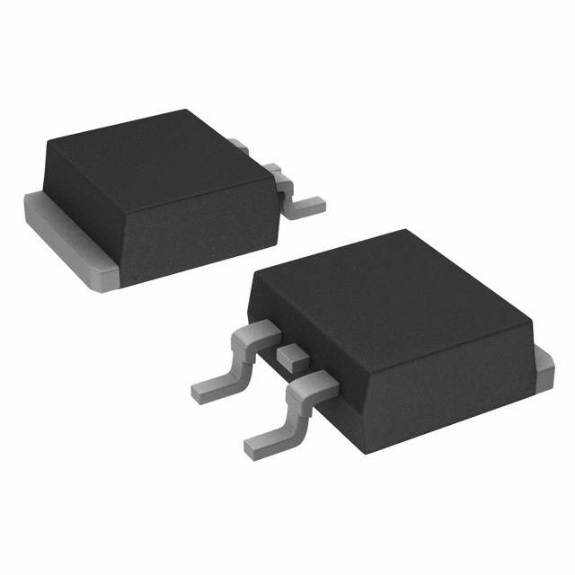
The IRFS4229PBF is an N-Channel MOSFET manufactured by Infineon Technologies, rated for 250V drain-to-source voltage and 45A continuous drain current in a surface mount D2PAK package. This device is part of the HEXFET® series and is designed for high-power switching applications requiring robust thermal performance at 330W maximum power dissipation.
The IRFS4229PBF is currently discontinued at DiGi Electronics, necessitating identification of functionally equivalent substitute components. Equivalent parts must maintain compatibility with existing PCB layouts, thermal management requirements, and electrical performance specifications within the application's design margins.
Substiute Parts
Key Parameters
| Parameter | Value | Unit |
|---|---|---|
| Drain-to-Source Voltage (Vdss) | 250 | V |
| Continuous Drain Current (Id) @ 25°C | 45 | A (Tc) |
| On-State Resistance (Rds On) @ 26A, 10V | 48 | mOhm |
| Gate Threshold Voltage (Vgs(th)) @ 250µA | 5 | V |
| Gate Charge (Qg) @ 10V | 110 | nC |
| Maximum Power Dissipation (Tc) | 330 | W |
| Operating Temperature Range | -40 to 175 | °C (TJ) |
| Package Type | D2PAK (TO-263-3) | Surface Mount |
| Gate Voltage Maximum (Vgs) | ±30 | V |
| Input Capacitance (Ciss) @ 25V | 4560 | pF |
Substitute Part Grouping Explanation
Substitution eligibility for the IRFS4229PBF is determined by the following critical parameters:
Primary Compatibility Criteria:
- Drain-to-Source Voltage (Vdss): Must equal or exceed 250V
- Package Type: Must be D2PAK (TO-263-3) or mechanically compatible surface mount variant
- Continuous Drain Current (Id): Must support minimum 45A at 25°C
- On-State Resistance (Rds On): Lower values indicate improved performance; higher values acceptable within thermal budget
- Operating Temperature Range: Must encompass application requirements
- Gate Voltage Rating (Vgs): Must accommodate ±30V or greater
Substitution Logic: Parts are grouped as direct substitutes when they maintain the same voltage class (250V), package footprint compatibility, and current rating capability. Thermal performance (Power Dissipation) and gate charge characteristics influence switching speed and thermal management but do not disqualify substitution if the application thermal design accommodates the differences.
The three identified substitute parts meet these criteria with the following considerations:
- SUM45N25-58-E3: Exact current and voltage match (45A, 250V); identical package; active product status
- IXFA30N25X3: Reduced current rating (30A vs 45A); same voltage class; different thermal profile
- STB75NF20: Reduced voltage rating (200V vs 250V); higher current capability (75A); different thermal characteristics
Parameter Comparison
| Parameter | IRFS4229PBF | SUM45N25-58-E3 | IXFA30N25X3 | STB75NF20 |
|---|---|---|---|---|
| Manufacturer | Infineon | Vishay Siliconix | IXYS | STMicroelectronics |
| Vdss (V) | 250 | 250 | 250 | 200 |
| Id @ 25°C (A) | 45 | 45 | 30 | 75 |
| Rds On (mOhm) | 48 @ 26A, 10V | 58 @ 20A, 10V | 60 @ 15A, 10V | 34 @ 37A, 10V |
| Vgs(th) (V) | 5 @ 250µA | 4 @ 250µA | 4.5 @ 500µA | 4 @ 250µA |
| Gate Charge Qg (nC) | 110 @ 10V | 140 @ 10V | 21 @ 10V | 84 @ 10V |
| Vgs Max (V) | ±30 | ±30 | ±20 | ±20 |
| Ciss (pF) | 4560 @ 25V | 5000 @ 25V | 1450 @ 25V | 3260 @ 25V |
| Power Dissipation Max (W) | 330 | 375 | 176 | 190 |
| Operating Temperature (°C) | -40 to 175 | -55 to 175 | -55 to 150 | -50 to 150 |
| Package | D2PAK | D2PAK | TO-263AA | D2PAK |
| Product Status | Discontinued | Active | Active | Active |
| RoHS Compliance | ROHS3 | ROHS3 | ROHS3 | ROHS3 |
Engineering Selection Recommendations
SUM45N25-58-E3 (Vishay Siliconix TrenchFET®)
This is the primary recommended substitute for direct replacement of the IRFS4229PBF. The SUM45N25-58-E3 provides identical voltage (250V) and current (45A) ratings with D2PAK package compatibility. The part is currently in active production status with 15,913 units in stock, ensuring supply chain continuity. Operating temperature range extends to -55°C, exceeding the original specification. Power dissipation capability (375W) exceeds the original 330W rating. Gate charge is slightly elevated (140nC vs 110nC), resulting in marginally increased switching losses but within acceptable engineering margins for most applications. RoHS3 compliance and REACH unaffected status match the original part.
IXFA30N25X3 (IXYS HiPerFET™ Ultra X3)
This substitute is suitable for applications where continuous drain current requirements do not exceed 30A. The 250V voltage rating matches the original specification. The significantly lower gate charge (21nC vs 110nC) provides faster switching characteristics and reduced driver power requirements. However, the reduced current rating (30A vs 45A) and lower power dissipation (176W vs 330W) limit applicability to lower-power designs. Operating temperature maximum is reduced to 150°C. This part is appropriate only when application current demands are confirmed below 30A.
STB75NF20 (STMicroelectronics STripFET™)
This substitute is applicable only when the application voltage requirement is confirmed at 200V or lower. The reduced voltage rating (200V vs 250V) disqualifies this part for 250V-rated applications. The higher current capability (75A) and improved on-state resistance (34mOhm) provide superior performance in lower-voltage applications. Operating temperature range is -50°C to 150°C. This part should be selected only when voltage derating analysis confirms 200V adequacy.
Frequently Asked Questions (FAQ)
Q: Can the SUM45N25-58-E3 be used as a direct drop-in replacement for the IRFS4229PBF?
A: Yes. The SUM45N25-58-E3 maintains identical voltage (250V), current (45A), and D2PAK package specifications. Pin configuration is compatible. The slightly elevated gate charge (140nC vs 110nC) may require minor gate driver timing adjustments but does not prevent direct substitution in most applications.
Q: What is the primary limitation of the IXFA30N25X3 as a substitute?
A: The IXFA30N25X3 is rated for 30A continuous drain current, compared to 45A for the IRFS4229PBF. Applications requiring sustained current above 30A cannot use this part. Additionally, the maximum operating temperature is limited to 150°C versus 175°C for the original part.
Q: Why is the STB75NF20 not recommended as a primary substitute?
A: The STB75NF20 has a reduced drain-to-source voltage rating of 200V compared to the 250V specification of the IRFS4229PBF. This voltage derating disqualifies the part for applications designed for 250V operation unless the circuit design is verified to operate safely at 200V maximum.
Q: Are all substitute parts available in the same package footprint?
A: The SUM45N25-58-E3 and STB75NF20 are both available in D2PAK (TO-263-3) packages with identical pin configurations. The IXFA30N25X3 is supplied in TO-263AA (IXFA) variant, which maintains mechanical and electrical compatibility with D2PAK footprints on standard PCBs.
Q: What is the impact of different gate charge values on circuit performance?
A: Gate charge (Qg) determines the energy required to switch the MOSFET on and off. The SUM45N25-58-E3 has higher gate charge (140nC) than the original (110nC), requiring slightly more driver current or longer switching times. The IXFA30N25X3 has significantly lower gate charge (21nC), enabling faster switching and reduced driver power consumption. These differences affect switching losses and thermal performance but do not prevent substitution if the gate driver is rated for the required charge.
Q: Are all substitute parts RoHS compliant?
A: Yes. All three substitute parts (SUM45N25-58-E3, IXFA30N25X3, and STB75NF20) are ROHS3 compliant and REACH unaffected, matching the environmental compliance status of the original IRFS4229PBF.
Q: Which substitute part offers the best thermal performance?
A: The SUM45N25-58-E3 provides the highest power dissipation rating (375W) among the substitutes, exceeding the original specification (330W). This part is optimal for thermally demanding applications. The STB75NF20 offers the lowest on-state resistance (34mOhm), which reduces conduction losses in high-current applications, though its lower voltage rating limits applicability.
Alternative Parts

SJ6012L2TP
Littelfuse Inc.
6 Alternative Parts

JMK107BBJ476MA-RE
Taiyo Yuden
10 Alternative Parts

GMK107BBJ475MA-T
Taiyo Yuden
5 Alternative Parts
SJ6020N2ARP
Littelfuse Inc.
3 Alternative Parts
SJ6025R2ATP
Littelfuse Inc.
4 Alternative Parts

2474-05L
API Delevan Inc.
1 Alternative Parts

4590R-684K
API Delevan Inc.
1 Alternative Parts

CM6560R-334
API Delevan Inc.
1 Alternative Parts

CM6460-104
API Delevan Inc.
1 Alternative Parts

5526-12
API Delevan Inc.
1 Alternative Parts