


Request Quote
(Ships tomorrow)
IRFS3307ZPBF N-Channel MOSFET 75V 120A Equivalent & Substitute Parts
Part Overview
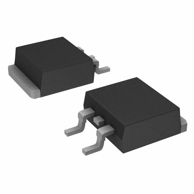
The IRFS3307ZPBF is an N-Channel MOSFET manufactured by Infineon Technologies, rated for 75V drain-to-source voltage with 120A continuous drain current at 25°C. This device is housed in a D2PAK (TO-263-3) surface mount package and delivers 230W maximum power dissipation. The part is discontinued at DiGi Electronics, necessitating identification of functionally equivalent alternatives from active product lines that maintain electrical and mechanical compatibility for direct board-level substitution.
Substiute Parts
Key Parameters
| Parameter | Value | Unit |
|---|---|---|
| Drain-to-Source Voltage (Vdss) | 75 | V |
| Continuous Drain Current (Id) @ 25°C | 120 | A (Tc) |
| On-Resistance (Rds On) @ 75A, 10V | 5.8 | mOhm |
| Gate Threshold Voltage (Vgs(th)) @ 150µA | 4 | V |
| Gate Charge (Qg) @ 10V | 110 | nC |
| Power Dissipation (Max) | 230 | W (Tc) |
| Operating Temperature Range | -55 to 175 | °C (TJ) |
| Package Type | D2PAK (TO-263-3) | Surface Mount |
| Technology | N-Channel MOSFET | Metal Oxide |
Substitute Part Grouping Explanation
Substitution of the IRFS3307ZPBF is determined by the following critical parameters:
Primary Substitution Criteria:
- Drain-to-Source Voltage (Vdss): Must equal or exceed 75V
- Continuous Drain Current (Id): Must equal or exceed 120A at 25°C
- Package Type: Must be D2PAK (TO-263-3) or mechanically compatible surface mount package
- Operating Temperature Range: Must span -55°C to 175°C minimum
- RoHS Compliance: ROHS3 Compliant status required
Secondary Compatibility Factors:
- On-Resistance (Rds On): Lower values indicate improved performance; values within ±30% of original are acceptable
- Gate Charge (Qg): Affects switching speed; values within ±50% maintain circuit behavior
- Power Dissipation: Must support thermal requirements of the application
Substitutes are grouped into two categories: Direct Equivalents (matching Vdss and Id specifications) and Functional Alternatives (meeting or exceeding electrical requirements with different voltage or current ratings).
Parameter Comparison
| Part Number | Manufacturer | Vdss (V) | Id @ 25°C (A) | Rds On (mOhm) | Qg (nC) | Pd Max (W) | Package | Status |
|---|---|---|---|---|---|---|---|---|
| IRFS3307ZPBF | Infineon | 75 | 120 | 5.8 @ 75A, 10V | 110 @ 10V | 230 | D2PAK | Discontinued |
| STB140NF75T4 | STMicroelectronics | 75 | 120 | 7.5 @ 70A, 10V | 218 @ 10V | 310 | D2PAK | Active |
| STB150NF55T4 | STMicroelectronics | 55 | 120 | 6 @ 60A, 10V | 190 @ 10V | 300 | D2PAK | Active |
| IPB054N08N3GATMA1 | Infineon | 80 | 80 | 5.4 @ 80A, 10V | 69 @ 10V | 150 | D2PAK | Active |
| IPB067N08N3GATMA1 | Infineon | 80 | 80 | 6.7 @ 73A, 10V | 56 @ 10V | 136 | D2PAK | Active |
| IPB049NE7N3GATMA1 | Infineon | 75 | 80 | 4.9 @ 80A, 10V | 68 @ 10V | 150 | D2PAK | Obsolete |
| STH140N8F7-2 | STMicroelectronics | 80 | 90 | 4 @ 45A, 10V | 96 @ 10V | 200 | H2PAK-2 | Active |
| FDB070AN06A0 | onsemi | 60 | 80 | 7 @ 80A, 10V | 66 @ 10V | 175 | D2PAK | Active |
| SQM110N05-06L_GE3 | Vishay Siliconix | 55 | 110 | 6 @ 30A, 10V | 110 @ 10V | 157 | D2PAK | Active |
Engineering Selection Recommendations
Primary Recommendation: STB140NF75T4
The STB140NF75T4 from STMicroelectronics is the closest functional equivalent. It matches the IRFS3307ZPBF in both Vdss (75V) and Id (120A) specifications, maintains D2PAK packaging, and is currently in active production status. The device is ROHS3 compliant with unlimited moisture sensitivity level. Higher power dissipation (310W vs. 230W) provides thermal margin. Slightly elevated on-resistance (7.5mOhm vs. 5.8mOhm) results in approximately 2.9% additional conduction losses at rated current, which is within acceptable engineering tolerance for most applications.
Secondary Recommendation: STB150NF55T4
The STB150NF55T4 maintains 120A continuous drain current and D2PAK packaging with active product status. The reduced Vdss rating (55V vs. 75V) limits this substitute to applications where the supply voltage does not exceed 55V. This part offers superior power dissipation (300W) and is widely available (10,200 pcs in stock). Selection requires verification that circuit operating voltage remains below 55V maximum.
Alternative for Lower Current Applications: IPB054N08N3GATMA1 or IPB067N08N3GATMA1
Both Infineon OptiMOS™ devices provide 80V Vdss with 80A continuous drain current in D2PAK packaging. These are suitable only for applications where 80A current capacity is sufficient. IPB054N08N3GATMA1 offers lower on-resistance (5.4mOhm) and higher gate charge (69nC), while IPB067N08N3GATMA1 provides reduced gate charge (56nC) with slightly higher on-resistance (6.7mOhm). Both are active products with high inventory availability.
Package Consideration: STH140N8F7-2
The STH140N8F7-2 from STMicroelectronics uses H2PAK-2 packaging instead of D2PAK. This part is not a direct mechanical substitute without PCB redesign. It provides 80V/90A ratings with superior on-resistance (4mOhm) and is recommended only when package migration is feasible.
Voltage-Reduced Alternatives: FDB070AN06A0 and SQM110N05-06L_GE3
These parts operate at reduced Vdss ratings (60V and 55V respectively) and are suitable only for lower-voltage applications. FDB070AN06A0 provides 80A at 60V in D2PAK. SQM110N05-06L_GE3 delivers 110A at 55V in D2PAK with matching gate charge (110nC) to the original part. Selection of these alternatives requires confirmation that application voltage specifications do not exceed their respective Vdss ratings.
Compliance Status:
All recommended substitutes maintain ROHS3 compliance, unlimited moisture sensitivity level (MSL 1), and REACH unaffected status, matching the original part's regulatory requirements.
Frequently Asked Questions (FAQ)
Q: Can I use STB150NF55T4 as a direct replacement for IRFS3307ZPBF?
A: STB150NF55T4 is mechanically and electrically compatible in D2PAK packaging and matches the 120A current rating. However, its 55V Vdss rating is lower than the original 75V. This substitute is valid only if your circuit operates at voltages not exceeding 55V. If your application requires 75V capability, use STB140NF75T4 instead.
Q: What is the difference between IPB054N08N3GATMA1 and IPB067N08N3GATMA1?
A: Both devices are Infineon OptiMOS™ MOSFETs rated for 80V/80A in D2PAK packaging. IPB054N08N3GATMA1 has lower on-resistance (5.4mOhm) but higher gate charge (69nC), resulting in faster switching but higher gate drive requirements. IPB067N08N3GATMA1 has higher on-resistance (6.7mOhm) but lower gate charge (56nC), reducing gate drive power. Selection depends on whether your circuit prioritizes conduction losses or switching losses.
Q: Why does STB140NF75T4 have higher gate charge (218nC) than IRFS3307ZPBF (110nC)?
A: Gate charge is proportional to the device's input capacitance and switching characteristics. The STB140NF75T4's higher gate charge reflects its STripFET™ III technology, which trades increased gate charge for improved on-resistance and thermal performance. This requires higher gate drive current but does not prevent direct substitution in most applications.
Q: Can I use STH140N8F7-2 without changing my PCB layout?
A: No. STH140N8F7-2 uses H2PAK-2 packaging, which has different pin spacing and thermal tab configuration compared to D2PAK. Direct board-level substitution is not possible without PCB redesign. Use this part only if your design can accommodate package migration.
Q: Is FDB070AN06A0 suitable for a 75V application?
A: No. FDB070AN06A0 is rated for maximum 60V Vdss. Using it in a 75V circuit exceeds its voltage rating and risks device failure. This part is suitable only for applications with supply voltages not exceeding 60V.
Q: What does "Tc" mean in the current rating?
A: "Tc" indicates the current rating is specified at the case temperature (Tc) of 25°C under specified thermal conditions. This is the continuous drain current the device can sustain without exceeding its maximum junction temperature during steady-state operation.
Q: Are all substitute parts RoHS3 compliant?
A: Yes. All recommended substitute parts listed carry ROHS3 compliance certification, matching the original IRFS3307ZPBF. All are also REACH unaffected and carry MSL 1 (unlimited) moisture sensitivity level.
Q: Which substitute has the lowest on-resistance?
A: STH140N8F7-2 has the lowest on-resistance at 4mOhm (measured at 45A, 10V). However, this part uses H2PAK-2 packaging and is not a direct D2PAK substitute. Among D2PAK alternatives, IPB049NE7N3GATMA1 offers the lowest on-resistance at 4.9mOhm, though it is obsolete. For active D2PAK products, IPB054N08N3GATMA1 provides 5.4mOhm.
Q: Can I parallel multiple lower-current MOSFETs to replace the 120A IRFS3307ZPBF?
A: Paralleling is not addressed in this substitution guide. Parallel MOSFET configurations require additional design considerations including gate drive distribution, current sharing networks, and thermal management beyond the scope of direct part substitution.
Alternative Parts

SJ6012L2TP
Littelfuse Inc.
6 Alternative Parts

JMK107BBJ476MA-RE
Taiyo Yuden
10 Alternative Parts

GMK107BBJ475MA-T
Taiyo Yuden
5 Alternative Parts
SJ6020N2ARP
Littelfuse Inc.
3 Alternative Parts
SJ6025R2ATP
Littelfuse Inc.
4 Alternative Parts

2474-05L
API Delevan Inc.
1 Alternative Parts

4590R-684K
API Delevan Inc.
1 Alternative Parts

CM6560R-334
API Delevan Inc.
1 Alternative Parts

CM6460-104
API Delevan Inc.
1 Alternative Parts

5526-12
API Delevan Inc.
1 Alternative Parts