


Request Quote
(Ships tomorrow)
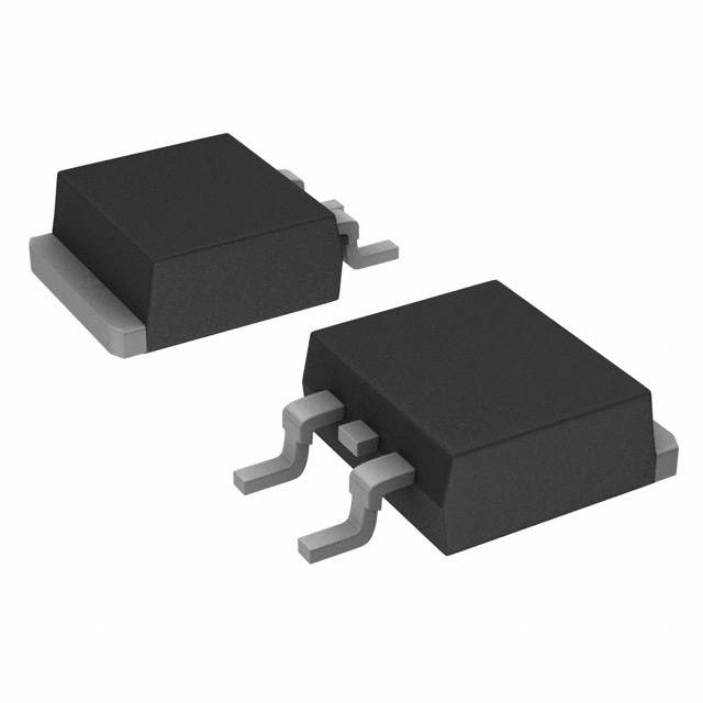
IRFS3307PBF N-Channel 75V 120A MOSFET Equivalent & Substitute Parts
Part Overview
The IRFS3307PBF is an N-Channel MOSFET manufactured by Infineon Technologies, rated for 75V drain-to-source voltage and 120A continuous drain current in a D2PAK surface mount package. This device is classified as obsolete product status. Due to its obsolescence, equivalent and substitute parts from active manufacturers are necessary to maintain design continuity and ensure long-term component availability for new production and field replacements.
Substiute Parts
Key Parameters
| Parameter | Value | Unit |
|---|---|---|
| Drain to Source Voltage (Vdss) | 75 | V |
| Continuous Drain Current (Id) @ 25°C | 120 | A (Tc) |
| Rds On (Max) @ Id, Vgs | 6.3 | mOhm @ 75A, 10V |
| Gate Charge (Qg) (Max) @ Vgs | 180 | nC @ 10V |
| Power Dissipation (Max) | 200 | W (Tc) |
| Operating Temperature Range | -55 to 175 | °C (TJ) |
| Package Type | D2PAK (TO-263-3) | Surface Mount |
| Vgs (Max) | ±20 | V |
Substitute Part Grouping Explanation
Substitution of the IRFS3307PBF is determined by the following critical parameters:
Primary Substitution Criteria:
- Drain-to-Source Voltage (Vdss): Must equal or exceed 75V
- Continuous Drain Current (Id): Must equal or exceed 120A at Tc
- Package Type: Must be D2PAK (TO-263-3) surface mount
- Operating Temperature Range: Must support -55°C to 175°C
- Gate Drive Voltage: Compatible with 10V drive voltage
Secondary Compatibility Factors:
- Rds On (Max): Lower or equal values indicate improved performance
- Gate Charge (Qg): Lower values reduce drive circuit stress
- Power Dissipation: Higher ratings provide thermal margin
- Vgs (Max): Must accommodate ±20V gate voltage
Substitute parts are grouped into two categories based on voltage and current ratings:
Category A - Direct Voltage/Current Match (75V, 120A): Parts maintaining 75V Vdss and 120A Id rating provide direct functional equivalence.
Category B - Voltage/Current Variants (60V-80V, 75A-100A): Parts with different voltage or current ratings require application-level verification but offer alternative solutions for designs with reduced voltage or current margins.
Parameter Comparison
| Part Number | Manufacturer | Vdss (V) | Id (A) @ Tc | Rds On (mOhm) | Qg (nC) | Pd (W) | Status | Package |
|---|---|---|---|---|---|---|---|---|
| IRFS3307PBF | Infineon | 75 | 120 | 6.3 @ 75A, 10V | 180 @ 10V | 200 | Obsolete | D2PAK |
| STB140NF75T4 | STMicroelectronics | 75 | 120 | 7.5 @ 70A, 10V | 218 @ 10V | 310 | Active | D2PAK |
| PSMN008-75B,118 | Nexperia USA Inc. | 75 | 75 | 8.5 @ 25A, 10V | 122.8 @ 10V | 230 | Active | D2PAK |
| BUK9609-75A,118 | NXP USA Inc. | 75 | 75 | 8.5 @ 25A, 10V | N/A | 230 | Active | D2PAK |
| PSMN5R0-80BS,118 | Nexperia USA Inc. | 80 | 100 | 5.1 @ 25A, 10V | 101 @ 10V | 270 | Active | D2PAK |
| PSMN6R5-80BS,118 | Nexperia USA Inc. | 80 | 100 | 6.9 @ 15A, 10V | 71 @ 10V | 210 | Active | D2PAK |
| SQM120N06-06_GE3 | Vishay Siliconix | 60 | 120 | 6 @ 30A, 10V | 145 @ 10V | 230 | Active | D2PAK |
| STB150NF55T4 | STMicroelectronics | 55 | 120 | 6 @ 60A, 10V | 190 @ 10V | 300 | Active | D2PAK |
| FDB5800 | onsemi | 60 | 80 | 6 @ 80A, 10V | 135 @ 10V | 242 | Active | D2PAK |
| STB100N6F7 | STMicroelectronics | 60 | 100 | 5.6 @ 50A, 10V | 30 @ 10V | 125 | Active | D2PAK |
Engineering Selection Recommendations
Primary Recommendation - Direct Equivalent:
STB140NF75T4 (STMicroelectronics) is the primary substitute for IRFS3307PBF. This part maintains identical voltage (75V) and current (120A) ratings with D2PAK packaging. The device is active product status with RoHS3 compliance and unlimited moisture sensitivity level. Higher power dissipation rating (310W vs. 200W) provides improved thermal performance. Gate charge specification (218 nC) is within acceptable range for 10V drive circuits.
Secondary Recommendations - Voltage/Current Variants:
PSMN5R0-80BS,118 and PSMN6R5-80BS,118 (Nexperia USA Inc.) offer 80V voltage rating with 100A current capability. These parts are suitable for applications where voltage margin above 75V is acceptable. Both devices feature active product status, RoHS3 compliance, and improved Rds On characteristics. PSMN5R0-80BS,118 provides superior on-resistance (5.1 mOhm) and lower gate charge (101 nC).
SQM120N06-06_GE3 (Vishay Siliconix) maintains 120A current rating with 60V voltage specification. This part is qualified to AEC-Q101 automotive standard and suitable for applications operating below 75V. Active product status and RoHS3 compliance are confirmed.
STB150NF55T4 (STMicroelectronics) provides 120A current at 55V voltage rating with superior power dissipation (300W). This part is suitable for lower-voltage applications and offers improved thermal characteristics.
Compliance and Certification Status:
All recommended substitute parts are active product status with RoHS3 compliance and unlimited moisture sensitivity level (MSL 1). Parts designated with AEC-Q101 qualification (SQM120N06-06_GE3, BUK9609-75A,118) are suitable for automotive applications.
Frequently Asked Questions (FAQ)
Q1: Can STB140NF75T4 directly replace IRFS3307PBF without circuit modification?
A: STB140NF75T4 maintains identical Vdss (75V) and Id (120A) ratings with D2PAK packaging. Both devices support ±20V gate voltage and operate across -55°C to 175°C temperature range. Direct substitution is supported at the component level. Circuit-level verification of gate drive timing and thermal management is recommended due to different Rds On and gate charge characteristics.
Q2: What is the voltage derating requirement when using PSMN5R0-80BS,118 or PSMN6R5-80BS,118 in place of IRFS3307PBF?
A: These parts feature 80V Vdss rating compared to 75V specification of IRFS3307PBF. No derating is required for applications operating at or below 75V. The additional 5V margin provides enhanced reliability in transient overvoltage conditions. Application-level verification of maximum drain-source voltage exposure is necessary.
Q3: Are there current rating limitations when substituting with SQM120N06-06_GE3?
A: SQM120N06-06_GE3 maintains 120A continuous drain current rating identical to IRFS3307PBF. The 60V voltage rating is the primary design constraint. This part is suitable only for applications where maximum drain-source voltage does not exceed 60V. Voltage margin analysis is required before selection.
Q4: What packaging considerations apply to all substitute parts?
A: All recommended substitute parts use D2PAK (TO-263-3) surface mount package with identical pinout and thermal tab configuration. PCB layout modifications are not required. Thermal interface material and heatsink mounting remain compatible across all listed parts.
Q5: How do gate charge differences affect circuit design?
A: IRFS3307PBF specifies 180 nC gate charge at 10V. Substitute parts range from 30 nC (STB100N6F7) to 218 nC (STB140NF75T4). Lower gate charge reduces gate drive circuit current requirements and switching losses. Higher gate charge increases drive circuit stress. Gate driver selection and PCB layout should be verified for parts with significantly different Qg specifications.
Q6: Which substitute part offers the lowest on-resistance?
A: PSMN5R0-80BS,118 provides the lowest Rds On specification at 5.1 mOhm (measured at 25A, 10V). This represents improved conduction efficiency compared to IRFS3307PBF at 6.3 mOhm (measured at 75A, 10V). Lower on-resistance reduces power dissipation and heat generation in high-current applications.
Q7: Are automotive-qualified alternatives available?
A: SQM120N06-06_GE3 (Vishay Siliconix) and BUK9609-75A,118 (NXP USA Inc.) are both qualified to AEC-Q101 automotive standard. These parts are suitable for automotive and industrial applications requiring third-party qualification documentation.
Q8: What is the thermal performance comparison between IRFS3307PBF and recommended substitutes?
A: IRFS3307PBF specifies 200W maximum power dissipation. STB140NF75T4 provides 310W, PSMN5R0-80BS,118 provides 270W, and STB150NF55T4 provides 300W. Higher power dissipation ratings indicate improved thermal performance and reduced junction temperature rise under identical operating conditions. Thermal management design should account for these differences.
Alternative Parts

SJ6012L2TP
Littelfuse Inc.
6 Alternative Parts

JMK107BBJ476MA-RE
Taiyo Yuden
10 Alternative Parts

GMK107BBJ475MA-T
Taiyo Yuden
5 Alternative Parts
SJ6020N2ARP
Littelfuse Inc.
3 Alternative Parts
SJ6025R2ATP
Littelfuse Inc.
4 Alternative Parts

2474-05L
API Delevan Inc.
1 Alternative Parts

4590R-684K
API Delevan Inc.
1 Alternative Parts

CM6560R-334
API Delevan Inc.
1 Alternative Parts

CM6460-104
API Delevan Inc.
1 Alternative Parts

5526-12
API Delevan Inc.
1 Alternative Parts