


Request Quote
(Ships tomorrow)
IRFS17N20DTRL Equivalent & Substitute Parts
Part Overview
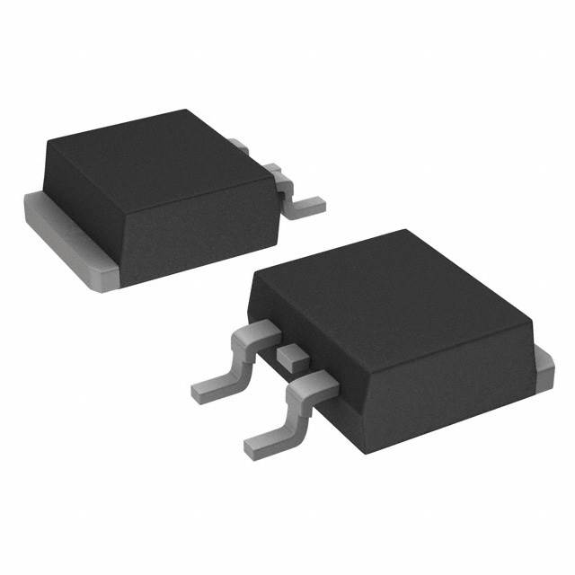
The IRFS17N20DTRL is an N-Channel MOSFET manufactured by Infineon Technologies, rated for 200V drain-to-source voltage with 16A continuous drain current in a D2PAK surface mount package. This device is classified as obsolete, making equivalent substitute parts necessary for new designs and production continuity. The part operates across a temperature range of -55°C to 175°C and is designed for applications requiring moderate power dissipation in compact surface mount form factors.
Substiute Parts
Key Parameters
| Parameter | Value | Unit |
|---|---|---|
| Drain-to-Source Voltage (Vdss) | 200 | V |
| Continuous Drain Current (Id) @ 25°C | 16 | A |
| On-State Resistance (Rds On) @ 10V | 170 | mOhm |
| Gate Threshold Voltage (Vgs(th)) @ 250µA | 5.5 | V |
| Gate Charge (Qg) @ 10V | 50 | nC |
| Input Capacitance (Ciss) @ 25V | 1100 | pF |
| Maximum Gate Voltage (Vgs) | ±30 | V |
| Power Dissipation (Ta) | 3.8 | W |
| Power Dissipation (Tc) | 140 | W |
| Operating Temperature Range | -55 to 175 | °C |
| Package Type | D2PAK (TO-263-3) | - |
| Mounting Type | Surface Mount | - |
Substitute Part Grouping Explanation
Substitution eligibility for the IRFS17N20DTRL is determined by the following critical parameters:
Primary Matching Criteria:
- Drain-to-Source Voltage (Vdss): Must equal 200V
- Package Type: Must be D2PAK or TO-263 equivalent
- Mounting Type: Must be Surface Mount
- FET Type: Must be N-Channel MOSFET
Secondary Compatibility Parameters:
- Continuous Drain Current (Id): Substitute must meet or exceed 16A
- On-State Resistance (Rds On): Lower or equivalent values acceptable
- Gate Threshold Voltage (Vgs(th)): Must be compatible with circuit drive voltage
- Maximum Gate Voltage (Vgs): Must accommodate circuit signal levels
- Operating Temperature Range: Must cover application requirements
All four substitute parts meet the primary matching criteria. Variations in secondary parameters reflect different device architectures and manufacturing processes while maintaining functional equivalence within the specified voltage and current ratings.
Parameter Comparison
| Parameter | IRFS17N20DTRL | IRF640STRLPBF | IRL640STRLPBF | RCJ160N20TL | STB19NF20 |
|---|---|---|---|---|---|
| Manufacturer | Infineon | Vishay Siliconix | Vishay Siliconix | Rohm Semiconductor | STMicroelectronics |
| Vdss (V) | 200 | 200 | 200 | 200 | 200 |
| Id @ 25°C (A) | 16 | 18 | 17 | 16 | 15 |
| Rds On @ 10V (mOhm) | 170 | 180 | 180 | 180 | 160 |
| Vgs(th) @ 250µA (V) | 5.5 | 4 | 2 | 5.25 | 4 |
| Qg @ 10V (nC) | 50 | 70 | 66 | 26 | 24 |
| Ciss @ 25V (pF) | 1100 | 1300 | 1800 | 1370 | 800 |
| Vgs Max (V) | ±30 | ±20 | ±10 | ±30 | ±20 |
| Power Dissipation Tc (W) | 140 | 130 | 125 | 40 | 90 |
| Operating Temperature (°C) | -55 to 175 | -55 to 150 | -55 to 150 | -55 to 150 | -55 to 150 |
| Package | D2PAK | TO-263 (D2PAK) | TO-263 (D2PAK) | LPTS | D2PAK |
| Product Status | Obsolete | Active | Active | Active | Active |
| RoHS Status | Non-compliant | ROHS3 Compliant | ROHS3 Compliant | ROHS3 Compliant | ROHS3 Compliant |
Engineering Selection Recommendations
IRF640STRLPBF (Vishay Siliconix)
This substitute provides the closest electrical match with 18A continuous drain current, exceeding the original 16A specification. The 200V Vdss rating and D2PAK package ensure direct mechanical compatibility. The device is in active production status with ROHS3 compliance, supporting modern manufacturing requirements. The slightly higher gate charge (70 nC vs. 50 nC) and input capacitance (1300 pF vs. 1100 pF) require verification in high-frequency switching applications. Maximum gate voltage of ±20V is lower than the original ±30V specification and must be confirmed compatible with circuit drive levels.
IRL640STRLPBF (Vishay Siliconix)
This substitute offers 17A continuous drain current with identical 200V Vdss rating and D2PAK package compatibility. The significantly lower gate threshold voltage (2V vs. 5.5V) indicates enhanced gate drive sensitivity, requiring circuit validation. The reduced maximum gate voltage (±10V vs. ±30V) is the most restrictive parameter and must be confirmed against application requirements. Higher input capacitance (1800 pF) may impact switching speed. Active production status and ROHS3 compliance support supply chain continuity.
RCJ160N20TL (Rohm Semiconductor)
This substitute maintains the original 16A continuous drain current specification with 200V Vdss rating. The LPTS package provides mechanical compatibility with D2PAK footprints. Notably lower gate charge (26 nC vs. 50 nC) and input capacitance (1370 pF) support faster switching characteristics. The maximum gate voltage specification of ±30V matches the original device. Power dissipation capability (40W Tc) is significantly reduced compared to the original (140W Tc), requiring thermal analysis for high-power applications. Active production status and ROHS3 compliance ensure supply availability.
STB19NF20 (STMicroelectronics)
This substitute provides 15A continuous drain current, slightly below the original 16A specification, with 200V Vdss rating and D2PAK package compatibility. The lowest on-state resistance (160 mOhm vs. 170 mOhm) and input capacitance (800 pF) offer improved efficiency and switching performance. Significantly lower gate charge (24 nC) supports faster gate drive response. The maximum gate voltage of ±20V is lower than the original specification. Power dissipation (90W Tc) is reduced from the original (140W Tc). Active production status and ROHS3 compliance support modern supply chains.
Frequently Asked Questions (FAQ)
Q: Can I use IRF640STRLPBF as a direct replacement for IRFS17N20DTRL?
A: IRF640STRLPBF is electrically compatible with the same 200V Vdss and D2PAK package. The 18A rating exceeds the original 16A specification. However, the maximum gate voltage (±20V vs. ±30V) must be verified against your circuit design. Gate charge and input capacitance are slightly higher, which may affect switching speed in high-frequency applications.
Q: What is the key difference between IRL640STRLPBF and IRF640STRLPBF?
A: Both devices share the same 200V Vdss, 17-18A current rating, and D2PAK package. The primary difference is gate threshold voltage: IRL640STRLPBF has 2V (low threshold) versus IRF640STRLPBF at 4V. The IRL640STRLPBF also has a lower maximum gate voltage (±10V vs. ±20V), which is a critical constraint for some applications.
Q: Why does RCJ160N20TL have lower power dissipation than the original part?
A: RCJ160N20TL uses LPTS (Low Profile Thin Shrink) packaging, which is a smaller form factor than standard D2PAK. The reduced thermal mass results in lower power dissipation capability (40W Tc vs. 140W Tc). This device is suitable for lower-power applications or designs with enhanced thermal management.
Q: Is STB19NF20 suitable for applications requiring 16A continuous current?
A: STB19NF20 is rated for 15A continuous drain current, which is 1A below the original 16A specification. For applications with strict 16A requirements, this device may not be suitable unless circuit design allows for the reduced current margin. Thermal analysis is recommended given the lower power dissipation rating (90W Tc).
Q: Are all substitute parts RoHS compliant?
A: Yes, all four substitute parts are ROHS3 compliant. The original IRFS17N20DTRL is RoHS non-compliant. Substitution with any of these parts supports modern manufacturing and environmental compliance requirements.
Q: Can I use these substitutes in high-temperature applications above 150°C?
A: The original IRFS17N20DTRL operates to 175°C. All four substitute parts are rated to 150°C maximum junction temperature, which is 25°C lower. Applications requiring operation above 150°C require alternative device selection or thermal management redesign.
Q: What is the impact of different gate threshold voltages on circuit design?
A: Gate threshold voltage (Vgs(th)) determines the minimum gate voltage required to turn the device on. IRL640STRLPBF (2V) requires lower drive voltage than IRFS17N20DTRL (5.5V), potentially allowing simpler gate drive circuits. However, lower threshold voltage increases susceptibility to parasitic turn-on. Circuit validation is required for each substitute.
Q: Do these substitutes have identical pinouts?
A: All substitute parts use D2PAK or LPTS packages, which are mechanically compatible with the original D2PAK footprint. Pinout is identical: Gate, Drain, and Source connections match across all devices. PCB layout changes are not required for package compatibility.
Alternative Parts

SJ6012L2TP
Littelfuse Inc.
6 Alternative Parts

JMK107BBJ476MA-RE
Taiyo Yuden
10 Alternative Parts

GMK107BBJ475MA-T
Taiyo Yuden
5 Alternative Parts
SJ6020N2ARP
Littelfuse Inc.
3 Alternative Parts
SJ6025R2ATP
Littelfuse Inc.
4 Alternative Parts

2474-05L
API Delevan Inc.
1 Alternative Parts

4590R-684K
API Delevan Inc.
1 Alternative Parts

CM6560R-334
API Delevan Inc.
1 Alternative Parts

CM6460-104
API Delevan Inc.
1 Alternative Parts

5526-12
API Delevan Inc.
1 Alternative Parts